
Related Manuals for Ametek Land SYSTEM 4


Summary of Contents for Ametek Land SYSTEM 4
- Page 1 Landmark for Profibus User Guide Issue 7 22 November 2016 Publication Nº 198.290 Language: English © Land Instruments International, 2016...
- Page 2 IMPORTANT INFORMATION - PLEASE READ Health and Safety Information Read all of the instructions in this booklet - including all the WARNINGS and CAUTIONS - before using this product. If there is any instruction which you do not understand, DO NOT USE THE PRODUCT.
- Page 3 Web: www.landinst.com For further details on all AMETEK Land offices, distributors and representatives, please visit our websites. Return of Damaged Goods IMPORTANT If any item has been damaged in transit, this should be reported to the carrier and to the supplier immediately.
- Page 4 Landmark for Profibus User Guide...
-
Page 5: Table Of Contents
User Guide Landmark for Profibus Contents Introduction About this guide 1.2 About the Landmark for Profibus Processor Unpacking the Processor Nomenclature Specification Installation and Removal Fitting the Unit Onto a DIN Rail Removing the Unit From a DIN Rail Electrical Connections Profibus DP Operation .gsd Files User Parameters 4.3 Configurable Cyclic Data Extended Diagnostics Time Function Processing... - Page 6 Landmark for Profibus User Guide...
-
Page 7: Introduction
User Guide Landmark for Profibus Introduction 1.1 About this guide This guide gives the information necessary for you to operate a Landmark for Profibus Signal Processor. Information regarding installation is contained within the Installation Guide. 1.2 About the Landmark for Profibus Processor The Landmark for Profibus Signal Processor provides an accurate signal processing unit for a single LAND System 4 thermometer on a master-slave Profibus DP network. The Landmark for Profibus processor can be set and run entirely from the Profibus DP master. Profibus DP has three states in it’s normal operating cycle: User Parameterisation Configuration Data Exchange 1.2.1 User Parameterisation In ‘User Parameterisation’, a one-off download of the operating parameters of the processor is carried out, including: • Emissivity / Non Greyness •... -
Page 8: Unpacking The Processor
Landmark for Profibus User Guide 1.2.4 Electrical Input/Output In addition to the Profibus data, the LMP provides electrical connections for the following: • Current output re-transmission of the thermometer signal, eg. 4 to 20 mA • Relay alarm output • Remote input for Track and Hold control or Peak Picker reset Unpacking the Processor The package containing the processor will contain the following items: •... -
Page 9: Specification
User Guide Landmark for Profibus Specification Input/output accuracy: < 0.1% of span Input/output drift: < 0.1% of span/°C Quantisation: 16 bit Sampling: 10ms Signal retransmission range: A djustable over thermometer span (min 100°) Signal retransmission current: 0 to 20mA/4 to 20mA Signal update rate: 1 0ms Current output load inc. cable: 500 ohms Emissivity setting: 0 .200 to 1.000 in 0.001 steps Non-greyness setting: 0 .800 to 1.250 in 0.001 steps Averager adjustment range: 50ms to 512s (63%) in 15 steps Peak Picker decay range: 0.25°/s to 512°/s in 12 steps threshold: 1° steps on delay: 0 to 10s in 0.1s steps off delay:... -
Page 10: Installation And Removal
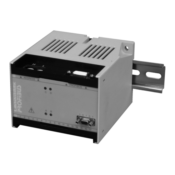
Landmark for Profibus User Guide Installation and Removal 3.1 Fitting the Unit Onto a DIN Rail The LMP processor is designed to be mounted onto a standard DIN rail. To install the unit: Ensure that a suitable DIN rail (DIN EN 50 022) is available and installed c orrectly (refer to Appendix). Refer to Fig. 2. Rest the uppermost groove on the rear of the processor on the top lip of the DIN rail. - Page 11 User Guide Landmark for Profibus DIN rail Clip onto DIN rail Sliding spring catch Fig. 2 Installing the LMP Processor Onto a DIN rail Use a screwdriver to unclip the spring latch Screwdriver Fig. 3 Removing the LMP Processor From a DIN rail Page 5...
- Page 12 Landmark for Profibus User Guide Slave Address Set Switches Profibus Connector 3 4 5 L N 11 12 13 14 15 16 Live Neutral Y BL W R BK GN Twisted Twisted Screened Twisted Pair Pair Pair Processor Supply (-) Processor Supply (+) Power Note...
- Page 13 User Guide Landmark for Profibus LM Technic Terminal Nº Wire Colour Function Yellow Signal input (+) from thermometer Blue Signal input (-) from thermometer White Emissivity output (+) to thermometer Screen Thermometer cable screen Thermometer power supply (+) Black Thermometer power supply (-) Green Emissivity return (-) • Not applicable - Do not use • Alarm relay (1) • Alarm relay (2) • Command (+) •...
- Page 14 Landmark for Profibus User Guide The cable connectors for the processor are included in the processor package. Each cable connector must be correctly wired with the appropriate cable. To correctly wire a connector: Make a note of the orientation of the connector. Unclip the two halves of the connector shell to reveal the terminal block and the cable tie/clamp bar.
- Page 15 User Guide Landmark for Profibus 3.3.2 CMD (Command) input connection schedule The CMD (Command) input connection schedule is given in Fig. 5 and Table 1. The command signal is inactive when the voltage is >3.0V or open circuit (i.e. Track). The command signal is active when the voltage is <1.5V or short circuit (i.e. Hold). The command input can be controlled via a remote switch, as shown in Fig. 6 or via potential-free contacts as shown in Fig.
- Page 16 Landmark for Profibus User Guide Remote switch Peak Picker Track & Hold Switch open Peak Pick Track Switch closed Reset Hold Note Remote switch can be replicated by voltage Vin. Where: >+3.0V = Switch open <+1.5V = Switch closed Fig. 6 CMD (Command) input control via a remote switch S4970387 Potential-free contacts...
-
Page 17: Profibus Dp Operation
User Guide Landmark for Profibus Profibus DP Operation This section gives details of how to apply the LMP to a Profibus DP System. It does not go into detail explaining Profibus DP. Further information can be found by visiting the designated website: www.profibus.com When the LMP processor is connected to a Land System 4 thermometer, the processor must be configured for use with that particular thermometer type. Profibus DP uses a ‘.gsd’ file as an electronic data sheet to allow the master processor to set up the operating parameters for the slave units attached to it’s network. 4.1 .gsd Files The Landmark for Profibus (LMP) is registered with the Profibus Nutzer Organisation (PNO) and has been designated with the special register number: LAND 0807. A .gsd file has also been allocated to this registration and is supplied on disk, with the processor. (LAND 0807.gsd). To allow access to the user parameters and cyclic data configuration of the processor, this .gsd file must be copied from the supplied disk to the gsd directory of the master system in use. 4.2 User Parameters User parameters are downloaded from the master system to the LMP, as a one-off at the start of Profibus operation. These user parameters are stored in a non-volatile memory within the LMP (if the LMP should lose power AND... - Page 18 Landmark for Profibus User Guide Page 12...
- Page 19 User Guide Landmark for Profibus Notes • If on-line access to a parameter is not required, set the LMP using the ‘User Parameters’ list. • A full, valid list of user parameters must be given, even if a particular parameter is not being used or is to be overwritten with cyclic data. • Ensure all parameters are within limits, as the LMP will reject any list containing ‘out of limit’ parameters.
- Page 20 Landmark for Profibus User Guide IRT Index IRT Type IRT Index IRT Type 0=LN 400/2000C 21=M6 100/700C 1=M1 600/1600C 22=M6 200/1300F 2=M1 1100/2900F 23=M7 25/375C 3=M1 800/2600C 24=M7 75/700F 4=M1 1500/4700F 25=LN 0/600C 5=M2 300/1100C 26=LN 0/1100C 6=M2 600/2000F 27=LN 0/1600C 7=M4 50/250C...
-
Page 21: Configurable Cyclic Data
User Guide Landmark for Profibus 4.3 Configurable Cyclic Data In Configuration, it is possible to organise the continuous reading and writing of cyclic data. The most obvious candidate for cyclic data is the ‘Temperature’ value. However, within the LMP it is also possible to select most of the user parameters for cyclic adjustment i.e. without having to re-initialise the Profibus DP system. When adjusting a parameter cyclically (eg. emissivity), the value overwrites the parameter that was written during ‘User Parameterisation’. However, it will only be stored in volatile memory. If power is lost, the LMP reverts to the user parameter version of the parameter until data-exchange is re-established when the cyclic value will be used again. - Page 22 Landmark for Profibus User Guide Module Name Size Description Temperature & Status 2 words I/P Word 1 - Temperature: 16 bit unsigned value of temperature in units as per IRT type Word 2 - Status: Bit 0-2: Not used Bit 3: 1=Command IP active / 0=Not active Bit 4: 1=Under range / 0=OK Bit 5: 1=Under range / 0=OK Bit 6: 1=Unclamped ratio IRT obscured / 0=OK Bit 7: 1=Clipping in averager / 0=OK...
-
Page 23: Extended Diagnostics
User Guide Landmark for Profibus Notes • IRT Type, Time Function Type and Current O/P Parameters are NOT available as cyclic data • Any configuration MUST include the Temperature and Status module • Only one of any type of module is allowed • It is common for there to be mismatches in the order of bytes within I/P and O/P words. Should this happen, use the CyclicDataByteOrder User Parameter to reverse the order of the bytes within a word from the LMP. • The user MUST NOT configure cyclic data for inactive parameters i.e: 1) Emissivity is only configurable if a single colour IRT (M type) has been selected in the User Parameters; 2) Non Greyness is only configurable if a two colour ratio IRT (R type) has been selected in the User Parameters; 3) Peak Picker parameters are only configurable if Peak Picker has been selected in the Time Function Select User Parameter; 4) Averager Response Time parameter is only configurable if Averager has been selected in the Time Function Select User Parameter •... -
Page 24: Time Function Processing
Landmark for Profibus User Guide Time Function Processing 5.1 Peak Picker The Peak Picker function can be used to monitor the highest temperature measured by the thermometer. This feature is useful especially for moving targets and/or where the target is obscured partially e.g. a steel slab on a rolling mill where parts of the surface are covered with scale. The ‘clean’ area will be at the higher (i.e. true) temperature. The Peak Picker used in Profibus processors has the following features. Refer to Fig. 9. Threshold level: Temperature above which the Peak Picker is active, used in conjunction with the ‘ON’ and ‘OFF’ delay. ON delay: Time period between the temperature rising above the threshold level and the Peak Picker function switching on OFF delay:... -
Page 25: Track And Hold
User Guide Landmark for Profibus 5.2 Track and Hold Time Track Hold Track Hold Command Command signal = Closure of potential-free contacts, s/c = Hold TTL level (0 to 5V) +5V = Track or 0 to 24V +24V = Track 0V = Hold Fig. -
Page 26: Averager
Landmark for Profibus User Guide 5.3 Averager Fast averager response speed Slow averager response speed Time Fig. 11 Graphical representation of the Averager time function S4970094 Refer to Fig. 11. The Averager time function can be used to ‘smooth’ the temperature output signal in relation to the temperature input. The averager response can be adjusted to suit your application. With a fast response speed, the temperature output signal tracks the input signal closely, any rapid fluctuations in the input are reflected in the output. -
Page 27: Led Indicators
User Guide Landmark for Profibus LED Indicators The external LEDs (A / B / C / D) on the LMP, give visual identification of internal operations of the unit. The following table lists the indications in order of precedence. LED A Colour Indication Amber Test Mode Flashing Amber Volatile Configuration Flashing Green Configurator Connected Green LED B Colour Indication Sensor Fail (Clamped pyrometers only) Flashing Red... -
Page 28: Maintenance
Landmark for Profibus User Guide Maintenance The LMP Processor is designed to be virtually maintenance free, but calibration checks are highly recommended at periods of not more than one year. For details on Landmark Technic calibration, please contact Land Instruments Calibration Services. Page 22... -
Page 29: Appendix A - Din Rail Specification
User Guide Landmark for Profibus Appendix A DIN rail specification. DIN EN 50 022. (See Fig. A-1 for DIN rail specifications) 27 ±0.2 27 ±0.2 7.5 0 7.5 0 1 ±0.04 1 ±0.04 -0.4 -0.4 35 ±0.3 35 ±0.3 Plain Punched RS Stock Nº Length RS Stock Nº Length 176-652 1.0m 424-131 0.5m 176-668 2.0m... -
Page 30: Appendix B - Using The Lmp Via The Config Port
Landmark for Profibus User Guide Appendix B - Using the LMP via the Config Port It is possible to use the LMP without Profibus - although customers are recommended to purchase a Landmark Technic, which provides this functionality at lower cost. To disable the Profibus function and use the configurator port, cable and software available from Land Instruments: • Switch off. • Remove all connections. • Remove the LMP from the DIN rail. •... - Page 31 User Guide Landmark for Profibus Installation Run the file on the CD and follow the Installation Instructions. Getting Started After the power supply has been connected and switched on, it is possible to configure the LMP using the configuration software. Connect the configurator cable between the PC and the LMP and run the software by running the .exe file in the installation directory. The configurator software should respond with the display as shown below. Fig. B1 Configurator Display Note This software is designed for use with Landmark Technic, but can be used with the LMP when in this mode. Configurator features key: Title bar indicating configuration file name A menu bar A ‘live’ display showing actual configuration and process data from the connected processor A ‘configuration area’ allowing parameters to be adjusted...
- Page 32 Landmark for Profibus User Guide Setting a New Configuration in a Processor New. Use the ‘File’, ‘New’, menu to load default data into the configuration area. Thermometer. In the configuration area, select the thermometer type from the list box to match the thermometer actually connected to the LMP. Note It is important that this is done first because it sets defaults and parameter limits in the other boxes. Label. Type in a label for the processor/thermometer (15 characters maximum). Emissivity/Non-Greyness. The menu changes dependent upon the selected thermometer. If a single colour thermometer has been selected, enter the desired emissivity for the material being measured.
-
Page 33: Appendix C - Serial Communications Set-Up
User Guide Landmark for Profibus Appendix C - Serial Communications Set-up The LMP configurator port can be used for communication between the processor and either a terminal or a computer. Note It is important that this is done first because it sets defaults and pa- rameter limits in the other boxes. RS232C is standard and compatible with either terminals or computers which allows communications with a single processor only. RS485 - contact Land Instruments International. - Page 34 Landmark for Profibus User Guide Serial Communications protocol RS232C read data Computer/Terminal Landmark Technic Parameter value being requested (ASCII) Value or requested parameter (ASCII) Fig. C1 RS232C mode READ protocol LMT010075 RS232C set data Landmark Technic Computer/Terminal Parameter value being modified (ASCII) Space New parameter...
- Page 35 User Guide Landmark for Profibus RS232C examples To read the temperature: Type at the terminal: RATMP [enter] Breakdown: Read mode Always A Command to report the temperature [enter] Press terminal enter key Reply: 1000 Temperature in degrees To set the emissivity to 0.500 Type at the terminal: SAEMS 500 [enter] Breakdown: Set mode Always A EMS Command to work on the emissivity value (Space) New value [enter] Press terminal enter key Reply: None NOTE In general, changed parameters are stored in volatile memory until an explicit save command is sent.
- Page 36 Landmark for Profibus User Guide Serial Port Parameters Range Name Menu title text Default Comments Increment Thermometer List of available type thermometers ob- tained using IFO command. Note Changing IRT sets default parameters in other places. Emissivity 1000 1000 e.g. Use of correct pa- 0.200 = 200 rameter is deter-...
- Page 37 User Guide Landmark for Profibus Range Name Menu title text Default Comments Increment Mode 0 = Low 1 = High Level irt_ irt_ irt_max Value in de- grees Signal output 0 = 0 to 20mA type 1 = 4 to 20mA Signal output irt_tmax = value in Additional limit...
- Page 38 Landmark for Profibus User Guide Range Menu title Name Increment Default Comments text Status flags Read only 0x0000 0xFFFF 0x0001 Function Command I/P Active Not active Under range Active Over range Active Obscured* Active Clipping** Active Sensor fail*** Active Alarm 1 Active Unclamped Ratio IRT only Average Node Only...
- Page 39 PRODUCT WARRANTY Thank you for purchasing your new product from Land Instruments International. This Land manufacturer’s ‘back-to-base’ warranty covers product malfunctions arising from defects in design or manufacture. The warranty period commences on the instrument despatch date from the Land Instruments International Ltd.
- Page 40 • Tel: +44 (0) 1246 417691 • Fax: +44 (0) 1246 410585 Email: land.enquiry@ametek.co.uk • www.landinst.com A M E T E K L a n d , I n c . • 1 5 0 F r e e p o r t R d .
Need help?
Do you have a question about the Land SYSTEM 4 and is the answer not in the manual?
Questions and answers