Chapters
Table of Contents

Related Manuals for Stahl 8404/2 Series


Summary of Contents for Stahl 8404/2 Series
- Page 1 Betriebsanleitung Operating instructions Additional languages www.stahl-ex.com DE EN Spannungsmesser Voltmeter Reihe 8404/2 Series 8404/2...
- Page 3 Betriebsanleitung Additional languages www.stahl-ex.com Spannungsmesser Reihe 8404/2...
-
Page 4: Table Of Contents
Inhaltsverzeichnis Allgemeine Angaben ...................3 Hersteller ......................3 Angaben zur Betriebsanleitung ................3 Weitere Dokumente ....................3 Konformität zu Normen und Bestimmungen ............3 Erläuterung der Symbole ..................3 Symbole in der Betriebsanleitung ...............3 Warnhinweise .....................4 Symbole am Gerät oder in Schaltplänen ............4 Sicherheitshinweise ....................5 Aufbewahrung der Betriebsanleitung ..............5 Sichere Verwendung ...................5 Umbauten und Änderungen ................5 Funktion und Geräteaufbau ................5... -
Page 5: De De
Diese ist rechtsverbindlich in allen juristischen Angelegenheiten. Weitere Dokumente • Datenblatt/Data sheet 8404/2 Weitere Sprachen, siehe www.stahl-ex.com. Konformität zu Normen und Bestimmungen Siehe Zertifikate und EG-Konformitätserklärung: www.stahl-ex.com. Erläuterung der Symbole Symbole in der Betriebsanleitung Symbol Bedeutung Tipps und Empfehlungen zum Gebrauch des Geräts Gefahr allgemein Gefahr durch explosionsfähige Atmosphäre... -
Page 6: 2.2 Warnhinweise
Erläuterung der Symbole Warnhinweise Warnhinweise unbedingt befolgen, um das konstruktive und durch den Betrieb bedingte Risiko zu minimieren. Die Warnhinweise sind wie folgt aufgebaut: • Signalwort: GEFAHR, WARNUNG, VORSICHT, HINWEIS • Art und Quelle der Gefahr/des Schadens • Folgen der Gefahr •... -
Page 7: Sicherheitshinweise
• Bei Installation und im Betrieb die Angaben (Kennwerte und Bemessungsbetriebsbedingungen) auf Typ- und Datenschildern sowie die Hinweisschilder am Gerät beachten. • Bei Betriebsbedingungen, die von den technischen Daten abweichen, unbedingt bei der R. STAHL Schaltgeräte GmbH rückfragen. Umbauten und Änderungen WARNUNG Gefahr durch Umbauten und Änderungen am Gerät! Explosionsschutz gefährdet! -
Page 8: 5 Technische Daten
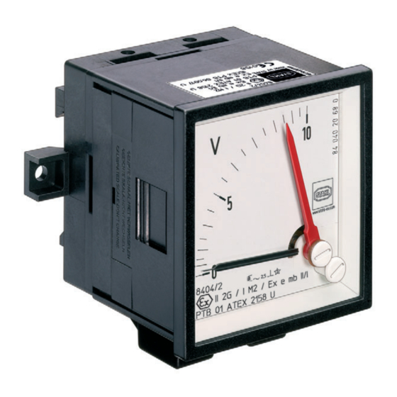
Material Gehäuse Polyamid, Polyester Schutzart Anschlüsse ohne Abdeckung: IP00 Anschlüsse mit Abdeckung: IP20 Messwerk Dreheisenmesswerk Skala Quadrantskala Länge 63 mm Montage / Installation Montage auf Tragschiene TS 35 Weitere technische Daten, siehe www.stahl-ex.com. Spannungsmesser 167771 / 8404602300 Reihe 8404/2 2014-02-25·BA00·III·de·01... -
Page 9: 6 Transport Und Lagerung
Transport und Lagerung Transport und Lagerung • Gerät nur in Originalverpackung transportieren und lagern. • Gerät trocken (keine Betauung) und erschütterungsfrei lagern. • Gerät nicht stürzen. Montage und Installation Maßangaben / Befestigungsmaße Maßzeichnung (alle Maße in mm [Zoll]) – Änderungen vorbehalten 67 [2,64] 80 [3,15] 89 [3,50]... -
Page 10: Montage / Demontage, Gebrauchslage
Montage und Installation Maßzeichnung (alle Maße in mm [Zoll]) – Änderungen vorbehalten 62 [2,44] +0,2 ø 4,5 +0,01 [ø 0,18 55 - [2,17 54 [2,13] 0,02 [2,44 72 [2,83] ±0,15 ±0,006 04655E00 05969E00 Spannungsmesser Reihe 8404/2 Montage / Demontage, Gebrauchslage Spannungsmesser immer in der gezeigten Lage einbauen. - Page 11 Inbetriebnahme Elektrischer Anschluss • Beachten Sie die Angaben in dem Kapitel „Technische Daten“. • Der Leiteranschluss ist mit besonderer Sorgfalt durchzuführen. • Die Leiterisolation muss bis an die Klemmstellen heranreichen. • Der Leiter darf beim Abisolieren nicht beschädigt (eingekerbt) werden. •...
-
Page 12: Betrieb
Betrieb Betrieb Nullpunkteinstellung Für den Fall, dass der schwarze Zeiger nach dem Einbau des Spannungsmessers bei 0 V nicht mehr in der Nullstellung steht, kann eine Nullpunkteinstellung vorgenommen werden. Voraussetzung: • Der Spannungsmesser ist eingebaut und spannungsfrei geschaltet. Nullpunkteinstellung: • Unten rechts den Nullpunkt mit der Schraube justieren. Messwertvergleich •... -
Page 13: 10.3 Reparatur
10.3 Reparatur GEFAHR Gefahr durch unsachgemäße Wartung/Reparatur! Explosionsschutz gefährdet! • Reparaturen am Gerät nur von R. STAHL Schaltgeräte GmbH durchführen lassen. 10.4 Rücksendung Für die Rücksendung im Reparatur-/Servicefall das Formular "Serviceschein" verwenden. Auf der Internetseite "www.stahl-ex.com" im Menü "Downloads >... - Page 15 Operating instructions Additional languages www.stahl-ex.com Voltmeter Series 8404/2...
- Page 16 Contents General Information ....................3 Manufacturer .......................3 Information Regarding the Operating Instructions ..........3 Further Documents .....................3 Conformity with Standards and Regulations ............3 Explanation of the Symbols ................3 Symbols in these Operating Instructions ............3 Warning Notes ....................4 Symbols on the Device or in the Circuit Diagrams ..........4 Safety Notes .......................5 Operating Instructions Storage ................5 Safe Use ......................5...
-
Page 17: En En
They are legally binding in all legal affairs. Further Documents • Datenblatt/Data sheet 8404/2 For further languages, see www.stahl-ex.com. Conformity with Standards and Regulations See certificates and EC Declaration of Conformity: www.stahl-ex.com. Explanation of the Symbols Symbols in these Operating Instructions Symbol Meaning... -
Page 18: 2.2 Warning Notes
Explanation of the Symbols Warning Notes Warning notes must be observed under all circumstances, in order to minimize the risk due to construction and operation. The warning notes have the following structure: • Signalling word: DANGER, WARNING, CAUTION, NOTICE • Type and source of danger/damage •... -
Page 19: Safety Notes
• During installation and operation observe the information (characteristic values and rated operating conditions) on the rating, data and information plates located on the device. • Always consult with R. STAHL Schaltgeräte GmbH in case of operating conditions which deviate from the technical data. Modifications and Alterations... -
Page 20: 5 Technical Data
Degree of protection Connections without cover: IP00 Connections with cover: IP20 Movement Moving iron Scale Quadrant scale Length 63 mm Mounting / Installation Mounting on mounting rail TS 35 For further technical data, see www.stahl-ex.com. Voltmeter 167771 / 8404602300 Series 8404/2 2014-02-25·BA00·III·en·01... -
Page 21: 6 Transport And Storage
Transport and Storage Transport and Storage • Transport and store the device only in the original packaging. • Store the device in a dry place (no condensation) and vibration-free. • Do not drop the device. Mounting and Installation Dimensions / Fastening Dimensions Dimensional drawings (all dimensions in mm [inch] –... -
Page 22: Mounting / Dismounting, Operating Position
Mounting and Installation Dimensional drawings (all dimensions in mm [inch] – Subject to alterations 62 [2,44] +0,2 ø 4,5 +0,01 [ø 0,18 55 - [2,17 54 [2,13] 0,02 [2,44 72 [2,83] ±0,15 ±0,006 04655E00 05969E00 Voltmeter Series 8404/2 Mounting / Dismounting, Operating Position The voltmeter must always be installed in the position shown. - Page 23 Commissioning Electrical Connection • The information given in chapter „Technical Data“ must be observed. • The conductor must be carefully connected. • The conductor insulation must reach to the clamping units. • The conductor must not be damaged (nicked) when removing the insulation. •...
-
Page 24: Operation
Operation Operation Zero point adjustment A zero point adjustment can be carried out, if the black pointer is not on the zero position at 0 V, after installing the voltmeter. Requirement: • The voltmeter is installed and disconnected from the power supply. Zero point adjustment: •... -
Page 25: 10.3 Repair
• Ensure environmentally friendly disposal of all components according to the statutory regulations. Accessories and Spare Parts NOTICE Use only original accessories and spare parts by R. STAHL Schaltgeräte GmbH. For accessories and spare parts, see data sheet on our homepage www.stahl-ex.com. 167771 / 8404602300 Voltmeter 2014-02-25·BA00·III·en·01... - Page 28 167771 / 8404602300 2014-02-25·BA00·III·de/en·01...
Need help?
Do you have a question about the 8404/2 Series and is the answer not in the manual?
Questions and answers