Stahl 8146/5075 Series Operating Instructions Manual
Grounding monitoring device
Hide thumbs
Also See for 8146/5075 Series:
- Manual (47 pages) ,
- Operating instructions manual (45 pages) ,
- Operating instructions manual (20 pages)
Chapters
Table of Contents

Subscribe to Our Youtube Channel
Related Manuals for Stahl 8146/5075 Series


Summary of Contents for Stahl 8146/5075 Series
- Page 1 Betriebsanleitung Additional languages www.r-stahl.com Erdungsüberwachungsgerät Reihe 8146/5075, Reihe 8150/5-V75...
-
Page 2: Table Of Contents
Inhaltsverzeichnis Allgemeine Angaben ...................3 Hersteller ......................3 Angaben zur Betriebsanleitung ................3 Weitere Dokumente ....................3 Konformität zu Normen und Bestimmungen ............3 Erläuterung der Symbole ..................3 Symbole in der Betriebsanleitung ...............3 Warnhinweise .....................4 Symbole am Gerät ....................4 Sicherheitshinweise ....................5 Aufbewahrung der Betriebsanleitung ..............5 Qualifikation des Personals ................5 Sichere Verwendung ...................5 Umbauten und Änderungen ................6... -
Page 3: De De
Diese ist rechtsverbindlich in allen juristischen Angelegenheiten. Weitere Dokumente • Datenblatt • FMEDA Report SIL Dokumente in weiteren Sprachen, siehe www.r-stahl.com. Konformität zu Normen und Bestimmungen Zertifikate und EU-Konformitätserklärung, siehe www.r-stahl.com. Das Gerät verfügt über eine IECEx-Zulassung. Zertifikat siehe IECEx-Homepage: http://iecex.iec.ch/... -
Page 4: 2.2 Warnhinweise
Erläuterung der Symbole Warnhinweise Warnhinweise unbedingt befolgen, um das konstruktive und durch den Betrieb bedingte Risiko zu minimieren. Die Warnhinweise sind wie folgt aufgebaut: • Signalwort: GEFAHR, WARNUNG, VORSICHT, HINWEIS • Art und Quelle der Gefahr/des Schadens • Folgen der Gefahr •... -
Page 5: Sicherheitshinweise
Normen und Bestimmungen umfasst. Für Tätigkeiten in explosionsgefährdeten Bereichen sind weitere Kenntnisse erforderlich! R. STAHL empfiehlt einen Kenntnisstand, der in folgenden Normen beschrieben wird: • IEC/EN 60079-14 (Projektierung, Auswahl und Errichtung elektrischer Anlagen) • IEC/EN 60079-17 (Prüfung und Instandhaltung elektrischer Anlagen) •... -
Page 6: Umbauten Und Änderungen
Funktion und Geräteaufbau Inbetriebnahme, Wartung, Reparatur • Inbetriebnahme und Instandsetzung nur durch qualifizierte und autorisierte Personen (siehe Abschnitt "Qualifikation des Personals") durchführen lassen. • Vor Inbetriebnahme sicherstellen, dass das Gerät unbeschädigt ist. • Nur Wartungsarbeiten durchführen, die in dieser Betriebsanleitung beschrieben sind. •... -
Page 7: Geräteaufbau
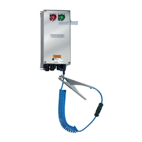
Funktion und Geräteaufbau Geräteaufbau 16525E00 16524E00 8146/5075 8150/5-V75 Gerätelement Beschreibung Kabelverschraubung Anschluss der Hilfsenergiespeisung. Kabelverschraubung Anschluss des potentialfreien Hilfskontaktes. Klimastutzen M25 / M20 Klimastutzen zur Belüftung und zum Druckausgleich von Ex e Gehäusen. Kabelverschraubung Anschlussverbindung zwischen der blauen Klemme (Pin 11) und M20 (Blau) der PA-Schiene der Verladeplattform. -
Page 8: Technische Daten
Technische Daten Technische Daten Explosionsschutz Ausführung 8146/5075 8150/5-V75 Global (IECEx) Gas und Staub IECEx PTB 06.0090 IECEx PTB 09.0049 Ex db e [ia Ga] IIC T4 Gb Ex d e [ia Ga] IIC T4 Gb Ex [ia Da] tb IIIC T80°C Db Ex tb IIIC T80°C Db Europa (ATEX) Gas und Staub... - Page 9 Technische Daten Technische Daten LED-Anzeige Funktionsweise: Zustand der Erdung Reaktion des Erdungs- überwachungsgerätes Zange ist nicht Erdung fehlerhaft angeschlossen, Gerät im • roter Leucht- Ruhezustand melder EIN • grüner Leucht- melder AUS • Schaltkontakt 10938E00 OFFEN Zange an Erdung in Ordnung Tankcontainer oder Fass •...
- Page 10 0,25 ... 2,5 mm Kunststoffhülse Kabel- Gewinde Klemmbereich verschraubungen 4 ... 13 mm 7 ... 17 mm Anzugsdrehmoment Gewinde Anzugsdrehmoment (bei 20 °C) 1,5 Nm 2,0 Nm Weitere technische Daten, siehe www.r-stahl.com. Erdungsüberwachungsgerät 137208 / 8146624300 Reihe 8146/5075, Reihe 8150/5-V75 2018-06-07·BA00·III·de·13...
-
Page 11: Projektierung
Projektierung Projektierung HINWEIS Ausfall der installierten Geräte im Schaltschrank durch zu hohe Umgebungstemperatur! Nichtbeachten kann zu Sachschäden führen. • Schaltschrank so aufbauen und einrichten, dass er immer innerhalb des zulässigen Temperaturbereichs betrieben wird. Transport und Lagerung • Gerät nur in Originalverpackung transportieren und lagern. •... -
Page 12: 8.1 Maßangaben / Befestigungsmaße
Montage und Installation Maßangaben / Befestigungsmaße Maßzeichnungen (alle Maße in mm [Zoll]) – Änderungen vorbehalten 08029E00 14867E00 Erdungsüberwachungsgerät Erdungsüberwachungsgerät 8146/5075 8150/5-V75 Erdungsüberwachungsgerät 137208 / 8146624300 Reihe 8146/5075, Reihe 8150/5-V75 2018-06-07·BA00·III·de·13... -
Page 13: Montage / Demontage, Gebrauchslage
Montage und Installation Montage / Demontage, Gebrauchslage Das Gerät ist für den Einsatz im Innen- und Außenbereich geeignet. • Bei Einsatz im Außenbereich Gehäuse und explosionsgeschütztes, elektrisches Betriebsmittel mit Schutzdach oder -wand ausrüsten. 8.2.1 Gebrauchslage 17202E00 17203E00 Gehäuse 8146 Gehäuse 8150 •... - Page 14 Montage und Installation 8.3.1 Elektrische Anschlüsse 18512E00 18511E00 Gehäuse 8146 Gehäuse 8150 • An das Erdungsüberwachungsgerät eine Zange mit normalen Kabel, Spiralkabel oder einer Aufrollautomatik anschließen. GEFAHR Explosionsgefahr durch falsche Auslegung der Kriech- und Luftstrecken! Nichtbeachten führt zu schweren oder tödlichen Verletzungen. •...
- Page 15 Montage und Installation 8.3.2 Prinzipschaltbild 18437E00 19411E00 Anschlussquerschnitte für anzuschließende Verdrahtung siehe Datenblatt. Legende 1 = Erdungsüberwachungsgerät 2 = Stromversorgung 3 = Potenzialfreier Hilfskontakt 4 = PA-Schiene der Verladeplattform 5 = Erdungszange oder Aufrollautomatik (Ex i Stromkreis) 137208 / 8146624300 Erdungsüberwachungsgerät 2018-06-07·BA00·III·de·13 Reihe 8146/5075, Reihe 8150/5-V75...
- Page 16 Montage und Installation HINWEIS Anschluss der Erdungszange an das Erdungsüberwachungsgerät (Ex i Stromkreis) Nichtbeachten kann Sachschäden verursachen! • Adern braun und grün/gelb werden in dem Anschlusskabel bzw. in der Aufrollautomatik zusammengeführt und an der PA Klemme angeschlossen. • Ader blau wird an der Klemme 10 angeschlossen. •...
- Page 17 Montage und Installation Zeitweilige Potentialausgleichsverbindungen umfassen Erdungsanschlüsse, die an beweglichen Einheiten, wie Trommeln, Fahrzeugen und tragbaren Betriebsmitteln für die Kontrolle der statischen Elektrizität oder den Potentialausgleich hergestellt werden Empfehlung: Endverbindung einer zeitweiligen Potentialausgleichsverbindung herstellen entweder: • in einem nicht explosionsgefährdeten Bereich; oder •...
-
Page 18: Inbetriebnahme
Inbetriebnahme Inbetriebnahme GEFAHR Explosionsgefahr durch fehlerhafte Installation! Nichtbeachten führt zu schweren oder tödlichen Verletzungen. • Gerät vor der Inbetriebnahme auf korrekte Installation prüfen. • Nationale Bestimmungen einhalten. Vor Inbetriebnahme Folgendes sicherstellen: • Montage und Installation kontrollieren. • Gehäuse auf Schäden untersuchen. •... -
Page 19: Anzeigen
Verdrahtung der Hilfsenergieversorgung Leuchtmelder erloschen kontrollieren. Wenn sich der Fehler mit den genannten Vorgehensweisen nicht beheben lässt: • An R. STAHL Schaltgeräte GmbH wenden. Zur schnellen Bearbeitung folgende Angaben bereithalten: • Typ und Seriennummer des Geräts • Kaufdaten • Fehlerbeschreibung •... -
Page 20: Instandhaltung, Wartung, Reparatur
Die geltenden nationalen Bestimmungen im Einsatzland beachten. 11.3 Reparatur GEFAHR Explosionsgefahr durch unsachgemäße Reparatur! Nichtbeachten führt zu schweren oder tödlichen Verletzungen. • Reparaturen an den Geräten ausschließlich durch R. STAHL Schaltgeräte GmbH ausführen lassen. Erdungsüberwachungsgerät 137208 / 8146624300 Reihe 8146/5075, Reihe 8150/5-V75 2018-06-07·BA00·III·de·13... -
Page 21: Rücksendung
Reinigung 11.4 Rücksendung • Rücksendung bzw. Verpackung der Geräte nur in Absprache mit R. STAHL durchführen! Dazu mit der zuständigen Vertretung von R. STAHL Kontakt aufnehmen. Für die Rücksendung im Reparatur- bzw. Servicefall steht der Kundenservice von R. STAHL zur Verfügung. - Page 23 Operating instructions Additional languages www.r-stahl.com Grounding monitoring device Series 8146/5075, Series 8150/5-V75...
- Page 24 Contents General Information ....................3 Manufacturer .......................3 Information regarding the Operating Instructions ..........3 Further Documents .....................3 Conformity with Standards and Regulations ............3 Explanation of the Symbols ................3 Symbols in these Operating Instructions ............3 Warning Notes ....................4 Symbols on the Device ..................4 Safety Notes .......................5 Operating Instructions Storage ................5 Personnel Qualification ..................5...
-
Page 25: En En
• FMEDA Report SIL For documents in additional languages, see www.r-stahl.com. Conformity with Standards and Regulations See certificates and EC Declaration of Conformity: www.r-stahl.com. The device has IECEx approval. For certificate please refer to the IECEx homepage: http://iecex.iec.ch/ Further national certificates can be downloaded via the following link: https://r-stahl.com/en/global/products/support/downloads/. -
Page 26: 2.2 Warning Notes
Explanation of the Symbols Warning Notes Warnings must be observed under all circumstances, in order to minimize the risk due to construction and operation. The warning notes have the following structure: • Signalling word: DANGER, WARNING, CAUTION, NOTICE • Type and source of danger/damage •... -
Page 27: Safety Notes
• Use the device in accordance with its intended and approved purpose only. • Always consult with R. STAHL Schaltgeräte GmbH if using the device under operating conditions which are not covered by the technical data. • Before installation, make sure that the device is not damaged. -
Page 28: Modifications And Alterations
Function and Device Design Commissioning, maintenance, repair • Only have commissioning and repairs performed by qualified and authorised persons (see "Personnel qualification" section). • Before commissioning, make sure that the device is not damaged. • Perform only maintenance work described in these operating instructions. •... -
Page 29: Device Design
Function and Device Design Device Design 16525E00 16524E00 8146/5075 8150/5-V75 Device component Description Cable gland M20 Connection of auxiliary power supply. Cable gland M20 Connection of potential-free auxiliary contact. Breather M25 / M20 Breather used for ventilation and pressure equalization of Ex e enclosures. -
Page 30: Technical Data
Technical Data Technical Data Explosion Protection Design 8146/5075 8150/5-V75 Global (IECEx) Gas and dust IECEx PTB 06.0090 IECEx PTB 09.0049 Ex db e [ia Ga] IIC T4 Gb Ex d e [ia Ga] IIC T4 Gb Ex [ia Da] tb IIIC T80°C Db Ex tb IIIC T80°C Db Europe (ATEX) Gas and dust... - Page 31 Technical Data Technical Data LED display Operating mode: State of grounding Reaction of the grounding monitoring device Clamp is not Grounding incorrect connected, device not in use • red indicator lamp • green indicator lamp • Switching contact 10938E00 OPEN Clamp connected Grounding ok to tank container or...
- Page 32 Thread Clamping range 4 to 13 mm 7 to 17 mm Tightening torque Threads Tightening torque (at 20 °C) 1.5 Nm 2.0 Nm For further technical data, see www.r-stahl.com. Grounding monitoring device 137208 / 8146624300 Series 8146/5075, Series 8150/5-V75 2018-06-07·BA00·III·en·13...
-
Page 33: Engineering
Engineering Engineering NOTICE An ambient temperature that is too high may cause failure of the devices installed in the cabinet. Non-compliance can result in material damage. • Install and adjust the cabinet in such a way that it is always operated within the permissible temperature range. -
Page 34: 8.1 Dimensions / Fastening Dimensions
Mounting and Installation Dimensions / Fastening Dimensions Dimensional Drawings (All Dimensions in mm [inches]) – Subject to Alterations 08029E00 14867E00 Grounding monitoring device Grounding monitoring device 8146/5075 8150/5-V75 Grounding monitoring device 137208 / 8146624300 Series 8146/5075, Series 8150/5-V75 2018-06-07·BA00·III·en·13... -
Page 35: Mounting / Dismounting, Operating Position
Mounting and Installation Mounting / Dismounting, Operating position This device is suitable for outdoor and indoor use. • Provide a protective roof or wall if the enclosure and explosion-protected electrical equipment are used outdoors. 8.2.1 Operating Position 17202E00 17203E00 Enclosure 8146 Enclosure 8150 •... - Page 36 Mounting and Installation 8.3.1 Electrical Connections 18512E00 18511E00 Enclosure 8146 Enclosure 8150 • Connect a clamp with normal cable, spiral cable or an automatic winder to the grounding monitoring device. DANGER Explosion hazard due to incorrect dimensioning of creepage distances and clearances! Non-compliance results in severe or fatal injuries.
- Page 37 Mounting and Installation 8.3.2 Schematic Diagram 18437E00 19411E00 For information on the connection cross-sections of the wiring to be connected, refer to the data sheet. Legend 1 = grounding monitoring device 2 = power supply 3 = potential-free auxiliary contact 4 = equipotential bonding rail of the loading platform 5 = grounding clamp or automatic winder (Ex i electric circuit) 137208 / 8146624300...
- Page 38 Mounting and Installation NOTICE Connecting the grounding clamp to the grounding monitoring device (Ex i electric circuit) Non-compliance can result in material damage! • Brown and green/yellow wires are merged in the connection cable or the automatic winder and then connected to the equipotential bonding terminal. •...
- Page 39 Mounting and Installation Temporary bonding includes grounding connections made at moveable units such as drums, vehicles and portable equipment for the control of static electricity or for equipotential bonding. Recommendation: It is recommended that the final connection of a temporary bonding connection should be made either: •...
-
Page 40: Commissioning
Commissioning Commissioning DANGER Explosion hazard due to incorrect installation! Non-compliance results in severe or fatal injuries. • Check the device for proper installation before commissioning. • Comply with national regulations. Before commissioning, ensure the following: • Check the mounting and installation. •... -
Page 41: Indications
Check the wiring of the auxiliary power indicator lamp off supply. If the error cannot be eliminated using the mentioned procedures: • Contact R. STAHL Schaltgeräte GmbH. For fast processing, have the following information ready: • Type and serial number of the device • Purchase information •... -
Page 42: Maintenance, Overhaul, Repair
DANGER Explosion hazard due to improper repair! Non-compliance results in severe or fatal injuries. • Repair work on the devices must be performed only by R. STAHL Schaltgeräte GmbH. Grounding monitoring device 137208 / 8146624300 Series 8146/5075, Series 8150/5-V75 2018-06-07·BA00·III·en·13... -
Page 43: Returning The Device
• Only return or package the devices after consulting R. STAHL! Contact the responsible representative from R. STAHL. R. STAHL's customer service is available to handle returns if repair or service is required. • Contact customer service personally. • Go to the www.r-stahl.com website.
Need help?
Do you have a question about the 8146/5075 Series and is the answer not in the manual?
Questions and answers