Stahl 8485 Operating Manual
Hide thumbs
Also See for 8485:
- Operating instructions manual (69 pages) ,
- Operating instructions manual (73 pages)

Related Manuals for Stahl 8485


Summary of Contents for Stahl 8485
- Page 1 Betriebsanleitung Operating manual Additional languages r-stahl.com Erdungsüberwachungsgerät 8485 Grounding Monitoring Device 8485...
-
Page 2: Table Of Contents
Maßangaben / Befestigungsmaße ..................17 Montage und Demontage ..................... 18 Installation ..........................19 Konfiguration und Inbetriebnahme für 8485 Rev. B ................27 Austausch des Geräts ......................27 Konfiguration über PC ......................27 10 Konfiguration und Inbetriebnahme für 8485 Rev. C................32 Austausch des Geräts ...................... - Page 3 Dimensions / fastening dimensions ..................56 Mounting and dismounting ....................57 Installation ..........................58 Configuration and commissioning for 8485 Rev. B ................66 Replacement of the device ....................66 Configuration over PC ......................66 10 Configuration and commissioning for 8485 Rev. C................71 Replacement of the device ....................
-
Page 4: Allgemeine Angaben
Die Originalbetriebsanleitung ist die deutsche Ausgabe. Diese ist rechtsverbindlich in allen juristischen Angelegenheiten. Weitere Dokumente Datenblatt 8485 Dokumente in weiteren Sprachen, siehe r-stahl.com Konformität zu Normen und Bestimmungen Zertifikate und EU-Konformitätserklärung, siehe r-stahl.com. Das Gerät verfügt über eine IECEx-Zulassung. Siehe IECEx-Homepage: http://iecex.iec.ch/... -
Page 5: Warnhinweise
Nichtbeachtung der Anweisung kann zu einem Sachschaden am Gerät und/oder seiner Umgebung führen. Symbole am Gerät oder in Schaltplänen Symbol Bedeutung CE-Kennzeichnung gemäß aktuell gültiger Richtlinie. 0158 Gerät gemäß Kennzeichnung für explosionsgefährdete Bereiche zertifiziert. Erdungsüberwachungsgerät Typ 8485 204166 / 848560300010 15.10.2018·BA00·III·en·10... -
Page 6: Sicherheitshinweise
Bei Betriebsbedingungen, die von den technischen Daten abweichen, unbedingt bei der R. STAHL Schaltgeräte GmbH rückfragen. Die Geräte (8485/1*1-42) in Zone 1, 2, 21, 22 oder außerhalb explosionsgefährdeter Bereiche installieren. Das Gerät nur an Betriebsmittel anschließen, in denen keine höheren Spannungen als 253 V AC (50 Hz) auftreten können. -
Page 7: Funktion Und Geräteaufbau
Entladungen in explosionsgefährdeten Bereichen zu verhindern, die beim Be- und Entladen von brennbaren Flüssigkeiten und staubförmigen Produkten von LKWs, Tankwagen, Eisenbahnwaggons, Containern, Fässern, und Big Bags (bei 8485 Rev. C) zu einer Entzündung führen können. Der Ableitwiderstand wird während der Verladung ständig überwacht und der Zustand der elektrostatischen Erdung über einen grünen und roten Leuchtmelder sowie bis zu 4... -
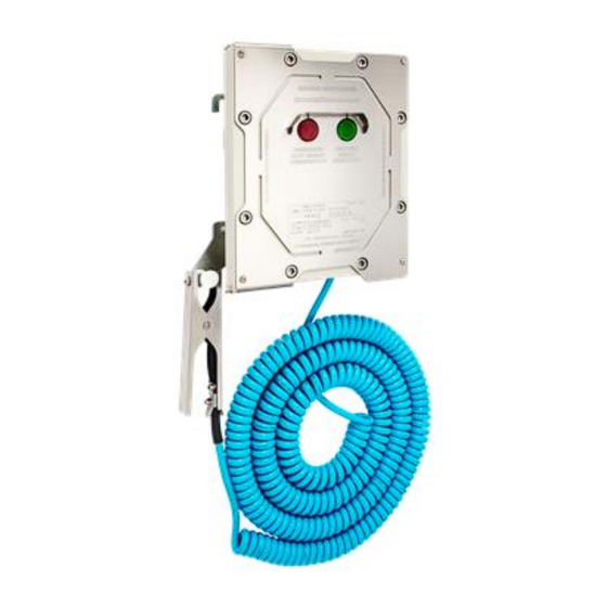
Page 8: Geräteaufbau
Kabelverschraubung M20 Anschluss des potentialfreien Hilfskontaktes Kabelverschraubung M20 Anschluss der Erdungszange mit Kabel oder Aufrollautomatik. Isolierter Aufhängepunkt Für sichere Verstauung der Zange. Signalisierung „Erdung nicht vorhanden“ Roter Leuchtmelder Signalisierung „Erdung vorhanden“ Grüner Leuchtmelder 204166 / 848560300010 Erdungsüberwachungsgerät Typ 8485 15.10.2018·BA00·III·en·10... -
Page 9: Funktionsbeschreibung Für 8485 Rev. B
Bild: 4.1 DIP-Schalter für die Einstellung des Erdungsobjektes 4.4.2. Verwendung des Erdungsgeräts für Tanklastzug (LKW) HINWEIS Elektrischer Anschlussplan, siehe Kapitel 8.3.2.1 für die Serie 8485/111-42 Rev. B Es werden zwei Parameter der elektrostatischen Erdung – Impedanz und ohmscher Widerstand ausgewertet. - Page 10 (z.B. über den Verladearm) 4.4.3. Verwendung des Erdungsgeräts für Schienentankfahrzeugen HINWEIS Elektrischer Anschlussplan, siehe Kapitel 8.3.2.1 für die Serie 8485/111-42 Rev. B Das Gerät 8485 kann zwischen zwei Zuständen unterscheiden: 1. Schienenfahrzeug (Kesselwagen) nicht angeschlossen oder die Impedanz > 3000 Ω –...
-
Page 11: Funktionsbeschreibung Für 8485 Rev. C
4.5.2. Verwendung des Erdungsgeräts für Tanklastzug (LKW) HINWEIS Elektrischer Anschlussplan, siehe Kapitel 8.3.2.2 für die Serie 8485/111-42 Rev. C Im Betrieb überwacht das Erdungsgerät zwei Erdungskomponenten - die Impedanz- und die Widerstandskomponente. Wenn der Wert im Bereich von 50 Ω bis 3000 Ω liegt, bewertet die Elektronik das System in Bezug auf elektrostatische Entladung als korrekt und der grüne Leuchtmelder leuchtet oder blinkt (Werkseinstellung: Dauerlicht). - Page 12 1. Die Zange wird am Erdungspunkt der Struktur oder am isolierten Aufhängepunkt angeschlossen. Der rote Leuchtmelder leuchtet. Die Relais R1 (RE1 & RE2) und R2 (RE3 & RE4) sind offen. Verladearm Filling Arm 8485/111-42 Rev. C Tanklastzug Road Tanker Zange Clamp 2.
- Page 13 *) Wenn der Widerstand der Erdungsschleife des Tankfahrzeugs < 10 Ω beträgt. 4.5.3. Verwendung des Erdungsgeräts für Schienentankfahrzeugen HINWEIS Elektrischer Anschlussplan, siehe Kapitel 8.3.2.2 für die Serie 8485/111-42 Rev. C Für Schienentankfahrzeuge treffen nur zwei Zustände zu: 1. Das Tankfahrzeug ist nicht angeschlossen oder die Impedanz > 3000 Ω (schlechte Verbindung) beträgt –...
- Page 14 4.5.4. Verwendung des Erdungsgeräts für mobile Anwendungen HINWEIS Elektrischer Anschlussplan, siehe Kapitel 8.3.2.3 für die Serie 8485/111-42 Rev. C Ein Fahrzeug wird über Zangen mit einem maximal 20 m langen Kabel am Erdungspunkt der Struktur angeschlossen. Es empfiehlt sich, das Fahrzeug mit einer Aufrollautomatik auszurüsten.
- Page 15 4.5.5. Verwendung des Erdungsgeräts für BIG BAGs - Typ C HINWEIS Elektrischer Anschlussplan, siehe Kapitel 8.3.2.4 für die Serie 8485/111-42 Rev. C In diesem Anwendungsbereich überwacht der Erdungsgerät kontinuierlich, ob ein Big-Bag einwandfrei an einem Erdungspunkt angeschlossen ist. Es ist erforderlich, wie im Folgenden beschrieben zu verfahren: ...
-
Page 16: Technische Daten
Kabelverschraubungen M20 x 1,5 Kommunikation Infrarot und Bluetooth (bei 8485 Rev. C) Relative Feuchte (keine Betauung) < 95 % Weitere technische Daten sind dem aktuellen Datenblatt zu entnehmen. *) Bei Temperatur kleiner als -40 °C muss das Gerät immer eingeschaltet bleiben. -
Page 17: Projektierung
Feuchte, Korrosion (siehe IEC/EN 60079-14). Gerät nur durch geschultes und mit den einschlägigen Normen vertrautes Fachpersonal installieren lassen. Maßangaben / Befestigungsmaße Erdungsüberwachungsgerät 8485/111-42 Erdungsüberwachungsgerät 8485/121-42 Bild 8.1 Maßzeichnung (alle Maße in mm) Erdungsüberwachungsgerät Typ 8485 204166 / 848560300010 15.10.2018·BA00·III·en·10... -
Page 18: Montage Und Demontage
Leuchtmelder ablesen kann. Gehäuse mit 4 Schrauben befestigen M10 (Anzugsmoment 35-40 Nm). An das Erdungsüberwachungsgerät ist eine Zange mit Kabel, Spiralkabel oder einer Aufrollautomatik angeschlossen. Bild 8.2 8485/1* Befestigungsmaße (alle Maße in mm) 204166 / 848560300010 Erdungsüberwachungsgerät Typ 8485 15.10.2018·BA00·III·en·10... -
Page 19: Installation
Der Anschluss der Erdungszangen / Aufrollautomatik erfolgt über den 2 = GND Anschlussbolzen des Erdungsgeräts. 3 = K2**) Die Installation ist durch Kabelverschraubung-Nr. 3*) durchzuführen *) die Kabelverschraubungszuordnungs-Nr. können Sie dem Kapitel 4.3 entnehmen. **) nur bei Big Bag Anwendung Erdungsüberwachungsgerät Typ 8485 204166 / 848560300010 15.10.2018·BA00·III·en·10... - Page 20 Im Falle von unzureichender Erdung ist es möglich Klemme Nr. 4 der Klemmleiste XC1 „Speisung“ mit dem PE Anschlusspunkt vom Gehäuse des 8485 zu verbinden, um eine korrekte Funktion des 8485 sicherzustellen 8.3.2.1 Elektrischer Anschlussplan von 8485/111-42 Rev. B (LKW und Kesselwagen) Erdungsüberwachungsgerät...
- Page 21 Montage und Installation 8.3.2.2 Elektrischer Anschlussplan Typ 8485/111-42 Rev. C (LKW und Kesselwagen) Erdungsüberwachungsgerät Grounding Monitoring Device 8485/111-42 Rev. C Hilfsenergie Relaisausgang R1 für K1 Relaisausgang R2 für 10 Ω Anschluss der Zangen Power supply Relay Output R1 for K1 Relay Output R2 for 10 Ω...
- Page 22 Montage und Installation 8.3.2.3 Elektrischer Anschlussplan Typ 8485/111-42 Rev. C (mobile Anwendung) Erdungsüberwachungsgerät Grounding Monitoring Device 8485/111-42 Rev. C Hilfsenergie Relaisausgang R1 für K1 Relaisausgang R2 für 10 Ω Anschluss der Zangen Power supply Relay Output R1 for K1 Relay Output R2 for 10 Ω...
- Page 23 Montage und Installation 8.3.2.4 Elektrischer Anschlussplan Typ 8485/111-42 Rev. C mit (Big Bag, Container, Fässern und IBCs) Erdungsüberwachungsgerät Grounding Monitoring Device 8485/111-42 Rev. C Hilfsenergie Relaisausgang R1 für K1 Relaisausgang R2 für 10 Ω Anschluss der Zangen Power supply Relay Output R1 for K1 Relay Output R2 for 10 Ω...
- Page 24 Bei der Auswahl bzw. Einsatz der Verschlussstopfen und Kabelverschraubung ist die Gewindeart und Größe zu beachten. Nur die von Firma R. Stahl zugelassenen und freigegebenen Kabelverschraubungen und Verschlussstopfen einzusetzen. Vor der Installation des Kabels muss ein Dichtring zwischen der Gehäusewand und dem Einführungsgewindestück eingesetzt werden.
- Page 25 Schleifenwiderstand weniger als 10 Ω beträgt Schrauben Sie die Kabelverschraubung fest Schrauben Sie das Einführungsgewindestück (1) in das Gehäuse ein, dann den Druckring (2) festschrauben. Bild: 8.9 Kabelverschraubung Erdungsüberwachungsgerät Typ 8485 204166 / 848560300010 15.10.2018·BA00·III·en·10...
- Page 26 8.3.8. Anschluss des Erdungspunkts an den Potentialausgleich PA Verbinden Sie den äußeren PA Punkt des Gehäuses mit einem gelb-grünen PE-Leiter (min. 4 mm²) zur Potentialausgleichsschiene der Verladeplattform. Bild: 8.10 Verbindung der äußeren PE Punkt des Gehäuses 204166 / 848560300010 Erdungsüberwachungsgerät Typ 8485 15.10.2018·BA00·III·en·10...
-
Page 27: Konfiguration Und Inbetriebnahme Für 8485 Rev. B
Schrauben der Scharniere festziehen. Alle Kabeleinführungen und Schrauben müssen korrekt festgezogen werden, um die Sicherheit des Ex d Gehäuses zu gewährleisten. 9 Konfiguration und Inbetriebnahme für 8485 Rev. B GEFAHR Explosionsgefahr durch fehlerhafte Installation! Nichtbeachten führt zu schweren oder tödlichen Verletzungen. - Page 28 Konfiguration und Inbetriebnahme für 8485 Rev. B Bild: 9.1 Konfigurationsset für IrDA-Schnittstelle Beachten Sie, dass die Konfiguration nur außerhalb des explosionsgefährdeten Bereichen bzw. nur mit Sondererlaubnis erfolgen darf 9.2.1. Konfigurationssoftware Die Konfigurationssoftware dient zur Einstellung von Parametern und zum Auslesen des Ist-Zustandes und der Werte vom A/D Wandler des Erdungsüberwachungsgeräts.
- Page 29 Konfiguration und Inbetriebnahme für 8485 Rev. B 9.2.2. Installation 2. Klicken Sie auf „NEXT“. 1. CD-ROM starten Die Installationsdatei setup.exe doppelklicken 3. Klicken Sie auf „NEXT“. 4. Klicken Sie auf „NEXT“. 5. Klicken Sie „Close“ um die Installation zu 8485 Rev. B beenden.
- Page 30 9.2.3. Nach dem Start Nach dem die Software gestartet wurde, liest die Software alle Grenzwerte, die Werte des A/D Wandlers und den jeweiligen Zustand des 8485 ein. Entsprechend des Zustandes leuchtet der rote oder grüne Leuchtmelder. 9.2.4. Einstellung der Grenzwerte Die Grenzwerte kann man durch Eintragen der Werte in die entsprechenden Felder und durch das Klicken auf die Schaltflächen über den Feldern „obere Grenze“...
- Page 31 9.2.9. Programm beenden Um das Programm zu Beenden bitte die Schaltfläche Ende per Mausklick betätigen. 9.2.10. Unterbrechung der Kommunikation zwischen 8485 und PC Dabei werden die Informationselemente inaktiv. Nach erneutem Aufbau der Kommunikation werden die Informationselemente wieder aktiv (siehe Bild: 9.3).
-
Page 32: Konfiguration Und Inbetriebnahme Für 8485 Rev. C
Konfiguration und Inbetriebnahme für 8485 Rev. C 10 Konfiguration und Inbetriebnahme für 8485 Rev. C GEFAHR Explosionsgefahr durch fehlerhafte Installation! Nichtbeachten führt zu schweren oder tödlichen Verletzungen. Gerät vor der Inbetriebnahme auf korrekte Installation und Funktion überprüfen. Nationale Bestimmungen einhalten. - Page 33 Konfiguration und Inbetriebnahme für 8485 Rev. C 10.2.2. Bluetooth-Schnittstelle Auf dem Erdungsgerät kann über ein PC oder ein Smartphone (mit Android) zugegriffen werden. Die Bluetooth-Schnittstelle kann mit einem DIP-Schalter eingeschaltet werden (Werkeinstellung deaktiviert). Beim aktivierten Zustand ist eine blaue LED an der Display- Platine an.
- Page 34 Konfiguration und Inbetriebnahme für 8485 Rev. C 10.2.4. Installation 2. Klicken Sie auf „NEXT“. 1. CD-ROM starten Die Installationsdatei setup.exe doppelklicken 3. Klicken Sie auf „NEXT“. 4. Klicken Sie auf „NEXT“. 5. Klicken Sie „Close“ um die Installation zu 8485 Rev. C beenden.
- Page 35 Konfiguration und Inbetriebnahme für 8485 Rev. C 10.2.5. Nach dem Start Beim Start erkennt das Programm automatisch die Sprachversion von Windows. Wenn eine nicht unterstützte Sprachversion von Windows erkannt wird, wird die englische Sprachversion eingestellt. Im Pull-Down-Feld “Sprachauswahl” kann die Sprachversion des Programms geändert werden (die derzeitigen Sprachversionen sind Englisch, Deutsch,...
- Page 36 Konfiguration und Inbetriebnahme für 8485 Rev. C 10.2.6. Werte des A/D-Wandlers Der A/D-Wandler nimmt einen unveränderbaren Wert zwischen 0 und 255 an. Dieser Wert ist nur unveränderbare informative Wert der aktuell gemessenen Fahrzeug Impedanz. Der Wert 0 bedeutet 0 Ohm Impedanz und der Wert 255 bedeutet unendliche Impedanz.
- Page 37 10.2.11. Programm beenden Um das Programm zu beenden, schließen Sie das Software-Fenster. 10.2.12. Unterbrechung der Kommunikation zwischen 8485 und PC Wenn die Kommunikation zwischen dem Erdungsgerät und dem PC unterbrochen wird, wechselt die Farbe der Kommunikationsstatusanzeige zu grau. Wenn die Kommunikation wiederhergestellt ist, blinkt die Anzeige hellblau.
-
Page 38: Betrieb- Und Betriebszustände
Aufhängepunkt zurückhängen. Anzeigen Entsprechende Leuchtmelder am Gerät zeigen den Betriebszustand des Geräts an (siehe auch Kapitel "Funktion und Geräteaufbau"). 11.2.1. 8485 Rev. B Farbe Grün Erdung vorhanden Die Erdung ist nicht vorhanden. Betankung kann gestartet werden. -
Page 39: Fehlerbeseitigung
Konfigurationssets oder einer Bluetooth-Schnittstelle an die Rahmenbedingungen ihrer Anwendungen anpassen. Wenn sich der Fehler mit den genannten Vorgehensweisen nicht beheben lässt: An die nächste Vertriebsniederlassung von R. STAHL Schaltgeräte GmbH wenden. Zur schnellen Bearbeitung folgende Angaben bereithalten; Typ und Seriennummer, Kaufdaten, Fehlerbeschreibung, Einsatzzweck... -
Page 40: Wartung
Reparatur GEFAHR Explosionsgefahr durch unsachgemäße Reparatur! Nichtbeachten führt zu schweren oder tödlichen Verletzungen. Reparaturen an den Geräten ausschließlich durch R. STAHL ausführen lassen Rücksendung Für die Rücksendung im Reparatur-/Servicefall das Formular "Serviceschein" verwenden. Auf der Internetseite "r-stahl.com" im Menü "Downloads > Kundenservice": ... - Page 41 Operating instructions Additional languages r-stahl.com Grounding Monitoring Device 8485...
- Page 42 Dimensions / fastening dimensions ..................56 Mounting and dismounting ....................57 Installation ..........................58 Configuration and commissioning for 8485 Rev. B ................66 Replacement of the device ....................66 Configuration over PC ......................66 10 Configuration and commissioning for 8485 Rev. C................71 Replacement of the device ....................
-
Page 43: General Information
Data sheet 8485 For further languages, see r-stahl.com. Conformity with standards and regulations See certificates and EU Declaration of Conformity: r-stahl.com. The device has IECEx approval. See IECEx homepage: http://iecex.iec.ch/ Further national certificates can be downloaded via the following link: https://r-stahl.com/en/global/support/downloads/... -
Page 44: Warning Notes
Symbols on the device or in the circuit diagrams Symbol Meaning CE marking according to the current applicable directive. 0158 Electric circuit certified for hazardous areas according to the marking. 204166 / 848560300010 Grounding Monitoring Device type 8485 15.10.2018·BA00·III·en·10... -
Page 45: Safety Notes
Always consult with R. STAHL Schaltgeräte GmbH if operating conditions deviate from the technical data. Install the devices (8485/1*1-42) in Zones 1, 2, 21, 22 or outside of hazardous areas. Connect the device only to equipment, which does not carry voltage higher than 253 V AC (50 Hz). -
Page 46: Function And Device Design
(dust) of road trucks, tankers, railway wagons, containers, barrels, drums and big bags (8485 Rev. C). The bleeder resistance is continuously monitored during loading and the state of electrostatic grounding is reported by means of a green and red indicator light as well as up to 4 potential-free contacts (change-over contacts). -
Page 47: Device Design
Connection of the grounding clamp with cable or automatic retractor. Insulated point of suspension For safe storage of the clamp. Red indicator light Signaling "Grounding not available" Green indicator light Signaling "Grounding available" Grounding Monitoring Device type 8485 204166 / 848560300010 15.10.2018·BA00·III·en·10... -
Page 48: Functional Description For 8485 Rev. B
Function and device design Functional description for 8485 Rev. B 4.4.1. Selection of the grounded object To select the object to be grounded (road tanker, rail vehicle), use the DIP switch with the designation K1 for channel 1. The following table describes the setting of the DIP switch:... - Page 49 Electric connection diagram, see chapter 8.3.2.1 of series 8485/111-42 Rev. B The device 8485 can differentiate between two states: Rail vehicle (tank wagon) is not connected or the impedance > 3000 Ω – red indicator light is lit. Rail vehicle (tank wagon) is connected and the impedance of the system is between 0 Ω...
-
Page 50: Functional Description For 8485 Rev. C
Function and device design Functional description for 8485 Rev. C 4.5.1. Selection of the grounded object To select the object to be grounded (road tanker, rail vehicle or Big Bag), use the DIP switch with the designation SU1. The following table describes the setting of the DIP... - Page 51 4. Disconnect the loading arm when the tanker is full and after that disconnect the clamp. Connect clamp to the Insulated point of suspension for clamps. The red indicator light is on. The relays R1 (RE1 & RE2) and R2 (RE3 & RE4) are de-energized. Grounding Monitoring Device type 8485 204166 / 848560300010 15.10.2018·BA00·III·en·10...
- Page 52 Electric connection diagram, see chapter 8.3.2.2 of series 8485/111-42 Rev. C The device 8485 can differentiate between two states: Rail vehicle (tank wagon) is not connected or the impedance > 3000 Ω (poor connection) – the red indicator light is on Rail vehicle (tank wagon) is connected and the impedance of the system is between 0 Ω...
- Page 53 Electric connection diagram, see chapter 8.3.2.3 of series 8485/111-42 Rev. C A vehicle is connected to the earth point of the structure by means of clamps with supply cable of maximum 20 m length. It is proper to furnish the vehicle with a reel for clamps supply cable.
- Page 54 NOTICE Electric connection diagram, see chapter 8.3.2.4 of series 8485/111-42 Rev. C In this area of application, the Grounding Device continuously monitors a proper connection of a big bag to a grounding point. It is necessary to follow next procedure 1) Connect the Grounding Device clamp to the big bag.
-
Page 55: Technical Data
Single-channel (Stainless steel) 17 kg Cable gland M20 x 1,5 Infrared and Bluetooth (8485 Rev. C) Relative humidity (no condensation) < 95 % Further technical data can be found in the current data sheet. *) At a temperature below -40 °C, the device must always remain in operation. -
Page 56: Project Engineering
The device must only be installed by trained qualified personnel who is familiar with the relevant standards. Dimensions / fastening dimensions Grounding monitoring device 8485/111-42 Grounding monitoring device 8485/121-42 Figure 8.1 Dimensional drawing (All dimensions in mm) 204166 / 848560300010 Grounding Monitoring Device type 8485 15.10.2018·BA00·III·en·10... -
Page 57: Mounting And Dismounting
Fasten the enclosure using 4 x M10 screws (Tightening torque 35-40 Nm). A clamp with cable, spiral cable or an automatic retractor is connected to the grounding monitoring device. Figure 8.2 fastening dimensions (All dimensions in mm) Grounding Monitoring Device type 8485 204166 / 848560300010 15.10.2018·BA00·III·en·10... -
Page 58: Installation
3 = K2**) The installation is to be done by cable gland no. 3*) *) The cable gland assignment numbers can be found in in chapter 4.3 **) Only for big bag application 204166 / 848560300010 Grounding Monitoring Device type 8485 15.10.2018·BA00·III·en·10... - Page 59 4 of the terminal strip XC1 "Supply" to the PE connecting point of the enclosure 8485 in order to ensure a correct function of 8485. 8.3.2.1 Electric connection diagram of 8485/111-42 Rev. B (Road tanker Rail Tank) Erdungsüberwachungsgerät Grounding Monitoring Device 8485/111-42 Rev.
- Page 60 Mounting and installation 8.3.2.2 Electric connection diagram of 8485/111-42 Rev. C (Road tanker / Rail Tank) Erdungsüberwachungsgerät Grounding Monitoring Device 8485/111-42 Rev. C Hilfsenergie Relaisausgang R1 für K1 Relaisausgang R2 für 10 Ω Anschluss der Zangen Power supply Relay Output R1 for K1 Relay Output R2 for 10 Ω...
- Page 61 Mounting and installation 8.3.2.3 Electric connection diagram of 8485/111-42 Rev. C (Mobile Applications) Erdungsüberwachungsgerät Grounding Monitoring Device 8485/111-42 Rev. C Hilfsenergie Relaisausgang R1 für K1 Relaisausgang R2 für 10 Ω Anschluss der Zangen Power supply Relay Output R1 for K1 Relay Output R2 for 10 Ω...
- Page 62 Mounting and installation 8.3.2.4 Electric connection diagram of 8485/111-42 Rev. C (BIG BAG, container, Barrels and IBCs) Erdungsüberwachungsgerät Grounding Monitoring Device 8485/111-42 Rev. C Hilfsenergie Relaisausgang R1 für K1 Relaisausgang R2 für 10 Ω Anschluss der Zangen Power supply Relay Output R1 for K1 Relay Output R2 for 10 Ω...
- Page 63 Single wire cross-section of the cable gland: rigid 2.5 mm² flexible 2.5 mm² flexible 1.5 mm² (with core end sleeve and plastic sleeve) flexible 2.5 mm² (with core end sleeve, without plastic sleeve) Grounding Monitoring Device type 8485 204166 / 848560300010 15.10.2018·BA00·III·en·10...
- Page 64 10 Ω Tighten the cable gland Screw in the male union (1) into the enclosure, and then tighten the pressure ring (2). Figure: 8.9 Cable gland for the grounding cable 204166 / 848560300010 Grounding Monitoring Device type 8485 15.10.2018·BA00·III·en·10...
- Page 65 Connect the external PA point of the enclosure with a yellow-green PE conductor (min. 4mm²) to the equipotential bonding rail of the loading platform. Figure: 8.10 Connection of the external PE point of the enclosure Grounding Monitoring Device type 8485 204166 / 848560300010 15.10.2018·BA00·III·en·10...
-
Page 66: Configuration And Commissioning For 8485 Rev. B
All glands and screws must be tightened correctly to ensure safety of the flameproof enclosure. 9 Configuration and commissioning for 8485 Rev. B DANGER Explosion hazard due to incorrect installation! Non-compliance results in severe or fatal injuries. - Page 67 Configuration and commissioning for 8485 Rev. B Figure: 9.1 The configuration set for IrDA interface Note that the configuration may be performed only outside the hazardous areas or only with a special permission. 9.2.1. Configuration software The configuration software serves for setting the parameters, reading out the actual status and the values of the A/D transducer of the grounding monitoring device.
- Page 68 Configuration and commissioning for 8485 Rev. B 9.2.2. Installation 1. Start CD-ROM 2. Click "NEXT". Double-click the installation file setup.exe 3. Click "NEXT". 4. Click "NEXT". 5. Click "Close" to complete the installation. 8485 Rev. B Software R. STAHL 8485, 7485 The USB drivers "FT232R USB UART"...
- Page 69 9.2.3. After the start After the software has been started, it reads in all limit values, the values of the A/D transducer and the corresponding state of 8485. The red or green indicator lights is lit depending on the state.
- Page 70 9.2.9. Quitting the program To quit the program please close the software window. 9.2.10. Interruption of the communication between 8485 and PC The information items become inactive during this process. Once the communication has been established again, the information items are activated again (see Bild: 9.3).
-
Page 71: Configuration And Commissioning For 8485 Rev. C
Configuration and commissioning for 8485 Rev. C 10 Configuration and commissioning for 8485 Rev. C DANGER Explosion hazard due to incorrect installation! Non-compliance results in severe or fatal injuries. Check the device for proper installation before commissioning. Comply with national regulations. - Page 72 Configuration and commissioning for 8485 Rev. C 10.2.2. Bluetooth interface The Bluetooth version of the Grounding Device can be accessed from a PC or a smart phone (based on Android OS). The Bluetooth interface can be switched on by a DIP switch (factory setting deactivated).
- Page 73 Configuration and commissioning for 8485 Rev. C 10.2.4. Installation 1. Start CD-ROM 2. Click "NEXT". Double-click the installation file setup.exe 3. Click "NEXT". 4. Click "NEXT". 5. Click "Close" to complete the installation. 8485 Rev. C Software STAHL 8485 APP: STAHL 8485 APP The USB drivers "FT232R USB UART"...
- Page 74 Configuration and commissioning for 8485 Rev. C 10.2.5. After the start The program automatically detects the language version of Windows while starting. If not supported language version of Windows is detected the English language version is set. It is possible to change the language version of the program by choosing a language version in the “Language Selection”...
- Page 75 Configuration and commissioning for 8485 Rev. C 10.2.6. Values of the A/D converter The A/D converter takes the value between 0 and 255, which cannot be changed. This value is only an informative value of the vehicle impedance. The value 0 means 0 Ohm impedance and the value 255 means infinite impedance.
- Page 76 10.2.11. Quitting the program To quit the program please close the software window. 10.2.12. Interruption of the communication between 8485 and PC When communication between the EGT and PC is interrupted, the communication status indicator changes the colour to grey. When communication is restored the indicator flashes in light blue colour.
-
Page 77: Operation And Operating States
The electrostatic charge is being discharged. After connection the loading arm, the road tanker is conductively connected to an earth point of the structure. If the resistance of grounding loop of tanker is < 10 Ω the green indicator light is on. Grounding Monitoring Device type 8485 204166 / 848560300010 15.10.2018·BA00·III·en·10... -
Page 78: Troubleshooting
If the error cannot be eliminated using the mentioned procedures: Contact the local representative of R. STAHL Schaltgeräte GmbH. For fast processing, have the following information ready: Type and serial number, purchase information, error description, purpose... -
Page 79: Overhaul
"r-stahl.com” under "Downloads > Customer service": Download the service form and fill it out. Send the device along with the service form in the original packaging to R. STAHL Schaltgeräte GmbH. 13 Cleaning To avoid electrostatic charging, the devices located in potentially explosive areas may only be cleaned using a damp cloth. -
Page 80: Eg Konformitätserklärung / Ec Declaration Of Conformity
16 EG Konformitätserklärung / EC Declaration of Conformity...
Need help?
Do you have a question about the 8485 and is the answer not in the manual?
Questions and answers