Table of Contents
Advertisement
Introduction
The 32F429IDISCOVERY Discovery kit allows users to easily develop applications with the
STMicroelectronics Arm
microcontroller. It includes an ST-LINK/V2-B embedded debug tool, a 2.4" QVGA TFT LCD,
an external 64-Mbit SDRAM, an ST MEMS gyroscope, a USB OTG Micro-AB connector,
LEDs and push-buttons.
The board comes with the STM32 comprehensive free software libraries and examples
available with the STM32CubeF4 MCU Package, as well as direct access to the Arm
™
Enabled
Picture is not contractual
July 2020
Discovery kit with STM32F429ZI MCU
®
Cortex
resources at the http://mbed.org website.
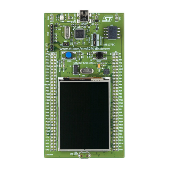
Figure 1. STM32F429 Discovery board
.
®
-M4 core-based STM32F429 high-performance
UM1670 Rev 4
UM1670
User manual
®
Mbed
www.st.com
1/32
1
Advertisement
Table of Contents

Related Manuals for ST 32F429IDISCOVERY


Summary of Contents for ST 32F429IDISCOVERY
-
Page 1: Figure 1. Stm32F429 Discovery Board
UM1670 User manual Discovery kit with STM32F429ZI MCU Introduction The 32F429IDISCOVERY Discovery kit allows users to easily develop applications with the ® ® STMicroelectronics Arm Cortex -M4 core-based STM32F429 high-performance microcontroller. It includes an ST-LINK/V2-B embedded debug tool, a 2.4" QVGA TFT LCD, an external 64-Mbit SDRAM, an ST MEMS gyroscope, a USB OTG Micro-AB connector, LEDs and push-buttons. -
Page 2: Table Of Contents
Mechanical drawing ......... 13 Embedded ST-LINK/V2-B ........14 6.3.1... - Page 3 Extension connectors ........22 32F429IDISCOVERY information ......29 Product marking .
- Page 4 List of tables UM1670 List of tables Table 1. Ordering information ............7 Table 2.
- Page 5 ST-LINK/V2-B connections ........
-
Page 6: Features
RAM in an LQFP144 package • 2.4" QVGA TFT LCD • USB OTG with Micro-AB connector • I3G4250D, ST MEMS motion sensor 3-axis digital output gyroscope • Six LEDs: – LD1 (red/green) for USB communication – LD2 (red) for 3.3 V power-on –... -
Page 7: Ordering Information
Table 1. Ordering information Order code Board reference Target STM32 STM32F429I-DISC1 MB1075 STM32F429ZIT6 ™ 1. Mbed Enabled STM32F429I-DISC1 with ST-LINK/V2-B replaces obsolete STM32F429I-DISCO with ST-LINK/V2. Codification The meaning of the codification is explained in Table Table 2. Codification explanation 32XXYYZDISCOVERY Description Example: 32F429IDISCOVERY... -
Page 8: Development Environment
STM32 Flash memory for easy demonstration of the device peripherals in standalone mode. The latest versions of the demonstration source code and associated documentation can be downloaded from www.st.com. Conventions Table 3 provides the definition of some conventions used in the present document. -
Page 9: Quick Start
Ensure that the jumpers JP3 and CN4 are set ON (Discovery mode). Connect the STM32F429 Discovery board to a PC using a USB cable Type-A/Mini-B through the USB ST-LINK connector CN1, to power the board, the LEDs LD2 (PWR) and LD1 (COM). -
Page 10: Hardware Layout
The STM32F429 Discovery board has been designed around the STM32F429ZIT6 microcontroller in a 144-pin LQFP package. Figure 2 illustrates the connections between the STM32F429ZIT6 and its peripherals (ST-LINK/V2-B, push-buttons, LEDs, USB OTG, ST-MEMS gyroscope, accelerometer, magnetometer, and connectors). Figure 3 Figure 4 show the location of these features on the STM32F429 Discovery board. -
Page 11: Stm32F429 Discovery Board Layout
Hardware layout STM32F429 Discovery board layout Figure 3. Top layout ST-LINK/V2-B PWR (red LED) COM (red/green LED) SWD connector measurement ST-LINK/DISCOVERY selector 3 V power supply input/output user button reset button (orange LED) (B2 – RESET) (green LED) 2.4" TFT LCD... -
Page 12: Figure 4. Bottom Layout
Hardware layout UM1670 Figure 4. Bottom layout SB12 (NRST) SB3, SB5, SB7, SB13 (RESERVED) SB11 (RX, TX) SB4, SB6, SB8, SB14 SB10 (STM_RST) (DEFAULT) SB9 (SWO) SB15 (RX, TX) SB19, SB20 SB16, SB17 (X3 crystal) (X2 crystal) SB18 (MCO) SB21 (BOOT1) SB22, SB23, SB24, SB25 STM32F429ZIT6... -
Page 13: Mechanical Drawing
UM1670 Hardware layout Mechanical drawing Figure 5. STM32F429 Discovery board mechanical drawing UM1670 Rev 4 13/32... -
Page 14: Embedded St-Link/V2-B
Embedded ST-LINK/V2-B The ST-LINK/V2-B on STM32F429I-DISC1 is embedded as a programming and debugging tool. Virtual COM port and USB mass storage features are supported by the ST-LINK/V2-B only for Mbed compatibility. The ST-LINK/V2-B makes the STM32F4429I-DISC1 boards Mbed Enabled. The embedded ST-LINK/V2-B supports only SWD for STM32 devices. -
Page 15: Drivers
The ST-LINK/V2-B embeds a firmware upgrade mechanism for the in-situ upgrade through the USB port. As the firmware may evolve during the lifetime of the ST-LINK/V2-B product (for example new functionalities, bug fixes, support for new microcontroller families), it is recommended to visit the www.st.com... -
Page 16: Using St-Link/V2-B To Program/Debug
Hardware layout UM1670 6.3.4 Using ST-LINK/V2-B to program/debug the STM32F429ZIT6 on board To program the STM32F429ZIT6 on board, simply plug in the two jumpers on CN4, as shown marked in red in Figure 7, but do not use the CN2 connector as it could disturb the communication with the STM32F429ZIT6 of the STM32F429 Discovery board. -
Page 17: Using St-Link/V2-B To Program/Debug
6.3.5 Using ST-LINK/V2-B to program/debug an external STM32 application It is very easy to use the ST-LINK/V2-B to program the STM32 on an external application. Simply remove the two jumpers from CN4 as shown in Figure 8 and connect the application... -
Page 18: Power Supply And Power Selection
LEDs • LD1 COM: The LD1 default status is red. LD1 turns to green to indicate that communications are in progress between the PC and the ST-LINK/V2-B. • LD2 PWR: The red LED indicates that the board is powered. •... -
Page 19: Usb Otg Supported
• LD6 (red LED) indicates an overcurrent from a connected device Gyroscope MEMS (ST-MEMS I3G4250D) The I3G4250D is a low-power, three-axis angular rate sensor. It includes a sensing element and an IC interface able to provide the measured angular rate to the external world through the I C/SPI serial interface. -
Page 20: Osc Clock
The following information indicates all configurations for clock supply selection. • MCO from ST-LINK (from MCO of the STM32F429ZIT6) This frequency cannot be changed, it is fixed at 8 MHz and connected to PH0-OSC_IN of the STM32F429ZIT6. The configuration needed is: –... -
Page 21: Solder Bridges
B1 push-button is connected to PA0. SB2 (B1-USER) B1 push-button is not connected to PA0. STM32F429 USART1 is not connected to ST-LINK, so VCP is disabled (Default configuration on 32F429IDISCOVERY). SB11, 15 (RX,TX) STM32F429 USART1 is connected to ST-LINK, so VCP is enabled (default configuration on STM32F429I-DISC1). -
Page 22: Extension Connectors
Hardware layout UM1670 6.14 Extension connectors The male headers P1 and P2 can connect the STM32F429 Discovery board to a standard prototyping/wrapping board. STM32F429ZIT6 GPIOs are available on these connectors. P1 and P2 can also be probed by an oscilloscope, a logic analyzer, or a voltmeter. Table 7. - Page 23 UM1670 Hardware layout Table 7. STM32 pin description versus board functions (continued) STM32 pin Board functions PA11 PA12 PA13 PA14 PA15 PB10 PB11 PB12 UM1670 Rev 4 23/32...
- Page 24 Hardware layout UM1670 Table 7. STM32 pin description versus board functions (continued) STM32 pin Board functions PB13 PB14 PB15 PC10 PC11 PC12 PC13 PC14 24/32 UM1670 Rev 4...
- Page 25 UM1670 Hardware layout Table 7. STM32 pin description versus board functions (continued) STM32 pin Board functions PC15 PD10 PD11 PD12 PD13 PD14 PD15 UM1670 Rev 4 25/32...
- Page 26 Hardware layout UM1670 Table 7. STM32 pin description versus board functions (continued) STM32 pin Board functions PE10 PE11 PE12 PE13 PE14 PE15 PF10 PF11 PF12 PF13 26/32 UM1670 Rev 4...
- Page 27 UM1670 Hardware layout Table 7. STM32 pin description versus board functions (continued) STM32 pin Board functions PF14 PF15 PG10 PG11 PG12 PG13 PG14 PG15 UM1670 Rev 4 27/32...
- Page 28 Hardware layout UM1670 Table 7. STM32 pin description versus board functions (continued) STM32 pin Board functions 1. If SB27 is ON. 2. If SB26 is ON. 28/32 UM1670 Rev 4...
-
Page 29: 32F429Idiscovery Information
Any consequences deriving from such usage will not be at ST charge. In no event, ST will be liable for any customer usage of these engineering sample tools as reference designs or in production. -
Page 30: Known Limitations
4.7 KΩ resistors Updated CN6 footprint Line added on top silkscreen for CN5 when FPC is mounted Known limitations 7.3.1 MB1075-F429 Revision B01 ST-LINK update from ST-LINK/V2 to ST-LINK/V2-B Revision C01 EOL request for L3GD20 and STMPE811QTR 30/32 UM1670 Rev 4... -
Page 31: Revision History
Figure 7, and Figure 02-Jul-2020 – Table 4: Jumper states – Section 6.3.4: Using ST-LINK/V2-B to program/debug the STM32F429ZIT6 on board Section 6.3.5: Using ST-LINK/V2-B to program/debug an external STM32 application for connector CN2, and Table 6: Solder bridges for connector CN3. - Page 32 ST products and/or to this document at any time without notice. Purchasers should obtain the latest relevant information on ST products before placing orders. ST products are sold pursuant to ST’s terms and conditions of sale in place at the time of order acknowledgment.
Need help?
Do you have a question about the 32F429IDISCOVERY and is the answer not in the manual?
Questions and answers