Table of Contents
Advertisement
Introduction
This application note complements the information in the STM8L and STM8AL datasheets
by describing the minimum hardware and software environment required to build an
application around an STM8L or STM8AL 8-bit microcontroller device.
A brief description of the principal hardware components is given. The power supply,
analog-to-digital converter (ADC), clock management, and reset control are described in
some detail. In addition, some hardware recommendations are given. This application note
also contains detailed reference design schematics with descriptions of the main
components. The STM8 development tools and software toolchain are common to STM8L,
STM8S, STM8AL, and STM8AF and are presented in
describes how to set up the STM8 development environment. Finally,
list of relevant documentation and online support resources.
Product family
Microcontrollers
July 2013
Getting started with STM8L and STM8AL
Table 1. Applicable products
– STM8L051/52
– STM8L101
– STM8L151C2/K2/G2/F2 and STM8L151C3/K3/G3/F3
– STM8L151x4, STM8L151x6, STM8L152x4, STM8L152x6
– STM8L151x8, STM8L152x8, STM8L151R6, STM8L152R6, STM8L162R8,
STM8L162M8
– STM8AL313x, STM8AL314x, STM8AL316x, STM8AL3L4x, STM8AL3L6x
DocID16139 Rev 5
Application note
Section
8, and
Part numbers
AN3029
Section
9.
Section 10
Section 11
provides a
1/42
www.st.com
Advertisement
Table of Contents

Related Manuals for ST STM8L


Summary of Contents for ST STM8L
- Page 1 Getting started with STM8L and STM8AL Introduction This application note complements the information in the STM8L and STM8AL datasheets by describing the minimum hardware and software environment required to build an application around an STM8L or STM8AL 8-bit microcontroller device.
-
Page 2: Table Of Contents
Contents AN3029 Contents Hardware requirements summary ......6 Power supply ..........6 Power supply overview . - Page 3 AN3029 Contents Reference design ......... . 19 Component references .
- Page 4 List of tables AN3029 List of tables Table 1. Applicable products ............1 Table 2.
- Page 5 AN3029 List of figures List of figures Figure 1. Power supply ............7 Figure 2.
-
Page 6: Hardware Requirements Summary
Power supply Power supply overview The STM8L or STM8AL can be supplied through a 1.65 V to 3.6 V external source (1.8 V to 3.6 V for STM8L05xxx). For medium density STM8L15xxx, medium density STM8AL31xx/STM8AL3Lxx, and high density STM8L15xxx/STM8L162xx with BOR, the power supply must be above 1.8 V at power-on and can go down to 1.65 V at power-down. -
Page 7: Main Operating Voltages
V Main operating voltages STM8L and STM8AL devices are processed in 0.13 µm technology. The STM8L and STM8AL core and I/O peripherals need different power supplies. In fact, STM8L and STM8AL devices have an internal regulator with a nominal target output of 1.8 V. -
Page 8: Power-On/Power-Down Reset (Por/Pdr)
In addition, each power supply pair should be decoupled with filtering ceramic capacitors (C) at 100 nF with one chemical C (1..2 µF) in parallel on the STM8L/STM8AL devices. The ceramic capacitors should be placed as close as possible to the appropriate pins, or below the appropriate pins, on the opposite side of the PCB. -
Page 9: Analog-To-Digital Converter (Adc)
AN3029 Analog-to-digital converter (ADC) Analog-to-digital converter (ADC) This section does not apply to STM8L101xx devices. Analog power For some packages, the ADC unit has an independent, analog supply voltage, isolated on input pin V , which allows the ADC to accept a very clean voltage source. This analog voltage, V , should be identical to the digital voltage supply on pin V . -
Page 10: Clock Management
Internal clocks STM8L and STM8AL devices have two kinds of internal clock: A high speed internal clock (HSI) running at 16 MHz and a low speed internal clock (LSI) running at 38 kHz. After reset, the CPU starts with the internal RC (HSI clock signal) divided by 8, i.e. 2 MHz. -
Page 11: Figure 4. Hse Clock Sources
A typical value is in the range 5 to 6 R (resonator series resistance). To fine-tune the value, refer to AN2867 (Oscillator design guide for ST microcontrollers). The values of the load capacitors C and C are heavily dependent on the crystal type and frequency. -
Page 12: Lse Clock
Clock management AN3029 Recommendations In the PCB layout all connections should be as short as possible. Any additional signals, especially those that could interfere with the oscillator, should be locally separated from the PCB area around the oscillation circuit using suitable shielding. 4.3.2 LSE clock The low-speed external clock signal (LSE) can be generated from two possible clock... -
Page 13: Figure 6. Crystal/Ceramic Resonators
= 7 pF. To fine-tune the choice, refer to the g calculation in mcrit AN2867 (Oscillator design guide for ST microcontrollers). 2. OSC32_IN and OSC32_OUT pins can be used also as GPIO, but it is recommended not to use them as both RTC and GPIO pins in the same application. -
Page 14: Reset Control
Reset control AN3029 Reset control Reset management overview The reset pin is a 3.3 V bidirectional I/O. After startup it can be programmed by software to be used as a general purpose I/O. Its output buffer driving capability is fixed to Iol = 2 mA @ 0.45 V in the 1.8 V to 3.6 V range which includes a ~45 k pull-up. -
Page 15: Output Characteristics
AN3029 Reset control 5.1.1 Output characteristics • A valid pulse on the pin is guaranteed with a ≥ 20 ns pulse duration on the internal output buffer. • After a valid pulse is recognized, a pulse on the pin of at least 20 µs is guaranteed starting from the falling edge of A. -
Page 16: Hardware Reset Implementation
Reset control AN3029 Hardware reset implementation The STM8L and STM8AL do not require an external reset circuit to power-up correctly. Only a pull-down capacitor is recommended (see Figure 7). However, charging/discharging the pull-down capacitor through an internal resistor has a negative influence on the device power consumption. -
Page 17: Recommendations
AN3029 Recommendations Recommendations Printed circuit board For technical reasons, it is best to use a multi-layer PCB with a separate layer dedicated to the V and another layer to the V supply. This results in a good decoupling, as well as a good shielding effect. -
Page 18: Other Signals
User options STM8L and STM8AL devices have user option features that can be used for remapping or enabling/disabling an automatic reset or low speed watchdog. For more details, please refer to the product datasheets. -
Page 19: Reference Design
Reference Quantity Comments Refer to the ‘pinouts and pin description’ and ‘package characteristics’ sections of Microcontroller STM8L, STM8AL STM8L and STM8AL datasheets, to choose the right package Battery 1.65 V to 3.6 V Min 1.8 V when BOR is enabled Capacitor 1 µF... -
Page 20: Schematics
Reference design AN3029 Schematics Figure 10. Reference design To power LCD specifically V DD 2.5V<V LCD <3.6V 1uF OR V SS External reset circuit For noisy environment V DD Only if accurate High Speed V REF Oscillator is needed (see note 2) NRST V LCD 20pF... -
Page 21: Stm8 Development Tools
STM8L1526-EVAL for medium density STM8L15xxx and STM8AL31xx/STM8AL3Lxx, and STM8L1528-EVAL for high density STM8L15xxx/STM8L162xx) • If you use STM8L101-EVAL, you also need the HW SWIM debug interface "Rlink" from Raisonance and ST-Link or STice-SWIM. The debug interface ST-LINK is included in STM8L1526-EVAL and STM8L1528-EVAL. • STM8L-DISCOVERY Single wire interface module (SWIM) 8.1.1... -
Page 22: Swim Connector Pins
V DD V DD STM8 SWIM cable MS32528V1 Caution: It is recommended to place the SWIM header as close as possible to the STM8L/STM8AL device, as this minimizes any possible signal degradation caused by long PCB tracks. 22/42 DocID16139 Rev 5... -
Page 23: Stice Emulator
It is supported by the free STM8 toolset: IDE ST Visual Develop (STVD) programmer, ST Visual Programmer (STVP) and STM8 Assembler. Please refer to the STice emulator for STM8 for more details. -
Page 24: Stice In Emulation Configuration
The above accessories are not included with the STice system. To determine exactly what is required for any supported microcontroller, refer to the online product selector on www.st.com. Figure 14. STice in emulation configuration 24/42... -
Page 25: In-Circuit Programming And Debugging
Figure 15. In-circuit programming and debugging RLink and STLink RLink and STLink are debug tools that allow the STM8L evaluation board or any user application board with the SWIM interface to be connected to a host PC via USB for debugging and programming. -
Page 26: Stm8 Software Toolchain
STM8 software toolchain AN3029 STM8 software toolchain To write, compile and run the first software on an STM8L/STM8AL device, the following components of the software toolchain are required (see Figure 16): • Integrated development environment • Compiler • Firmware library (optional, used to ease the startup) Figure 16. -
Page 27: Integrated Development Environment
STVD is delivered as part of the free ST toolset, which also includes the ST Visual Programmer (STVP) programming interface and ST Assembler-Linker. -
Page 28: Setting Up The Stm8 Development Environment
C compiler ST toolset STM8 firmware library ST-LINK does not need any dedicated software installation in the STM8 development environment because the necessary drivers are delivered with the ST toolset. The R-link drivers must be launched separately as follows: Start/Programs/STtoolset/Setup/Install Rlink driver. -
Page 29: Using The Tools
Setting up the STM8 development environment 10.2 Using the tools Once the tools installation is complete, the ST Visual Develop (STVD) integrated development environment can be launched. The user then has the choice to generate either a new workspace with a new project or to open an existing workspace. -
Page 30: Project Editing
Setting up the STM8 development environment AN3029 10.2.1 Project editing All project source files are visible and can be edited (see Figure 18). Figure 18. STVD MCU edit mode 30/42 DocID16139 Rev 5... -
Page 31: Online Help
AN3029 Setting up the STM8 development environment 10.2.2 Online help An online help manual is available inside the firmware installation directory (see Figure to help the user understand the structure of the STM8 firmware library. Figure 19. STM8 firmware library online help manual DocID16139 Rev 5 31/42... -
Page 32: Running The Demonstration Software
Setting up the STM8 development environment AN3029 10.3 Running the demonstration software • Go to www.st.com/mcu and search for STM8L/STM8AL products • Choose STM8L1x-EVAL, STM8L1526-EVAL, or STM8L1528-EVAL firmware • Open the desired project workspace within the chosen demonstration firmware package. -
Page 33: Selecting The Correct Debug Instrument
AN3029 Setting up the STM8 development environment 10.3.2 Selecting the correct debug instrument In the example below, the Rlink tool is used for communicating via the SWIM interface with the on-board debug module of the STM8. The Rlink tool can be selected from the ‘Debug Instrument Selection’ list in the ‘Debug Instrument Settings’... -
Page 34: Connecting The Hardware
Setting up the STM8 development environment AN3029 10.3.3 Connecting the hardware The debug tool, STLink, is included on the STM8L1526-EVAL and STM8L1528-EVAL boards. You can connect the PC to the USB connector. This connection ensures the debug connection and the power. If the jumpers on the boards are no longer in the default position, please read the evaluation board user manuals to select power and debug support jumpers. -
Page 35: Figure 23. Connecting The Debug Instrument To The Stm8L152X-Eval Evaluation Board
AN3029 Setting up the STM8 development environment Figure 23. Connecting the debug instrument to the STM8L152x-EVAL evaluation board Caution: On the Rlink adapter board for STM8, the “SWIM” jumper must be set. If there is no pull-up on the application SWIM line, the “ADAPT” jumper is also set. The “PW-5V” and “12MHz” jumpers must not be set. -
Page 36: Starting The Debug Session
Setting up the STM8 development environment AN3029 10.3.4 Starting the debug session Debug mode can be entered by the command ‘Debug Start Debugging’ (see Figure 24). Figure 24. STVD: Starting the debug session 36/42 DocID16139 Rev 5... -
Page 37: Running The Software
AN3029 Setting up the STM8 development environment 10.3.5 Running the software After entering debug mode, the software can be started by the run command in the menu ‘Debug Run’ (see Figure 25). Figure 25. STVD: Run the software DocID16139 Rev 5 37/42... -
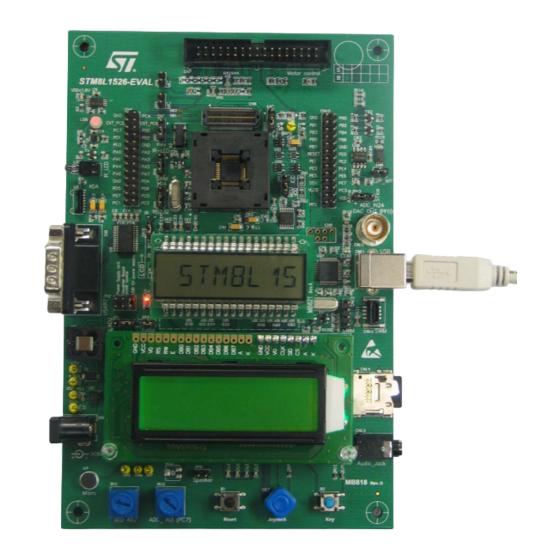
Page 38: Follow Up
Figure 26. STM8 evaluation board 10.3.6 Follow up Step by step, additional peripherals of STM8L/STM8AL devices can be run, following on from the initial debug session described above. Many features of STM8L/STM8AL devices are supported by dedicated hardware on the STM8 evaluation board. -
Page 39: Documentation And Online Support
Documentation and online support Documentation resources related to tool usage includes: Application • STM8L/STM8AL datasheets • How to program STM8L Flash program memory and data EEPROM (PM0054) • STM8 CPU programming manual (PM0044) • STM8L05xx, STM8L15xx, STM8L162x, STM8AL31xx and STM8AL3Lxx microcontroller family (RM0031) •... -
Page 40: Revision History
10: updated figure content and footnotes. Section 8: STM8 development tools: updated bullet point 5 regarding STM8L101-EVAL. Section 9.1: Integrated development environment: added the low- cost ST-Link tool in the list of hardware tools supported by STVD. 40/42 DocID16139 Rev 5... -
Page 41: Table 1. Applicable Products
AN3029 Revision history Table 4. Document revision history (continued) Date Revision Changes Document updated to include the STM8AL products. Added Table 1: Applicable products. 06-Nov-2012 Added note Table 2: Component list. Updated references in Section 8: STM8 development tools. Updated: 23-Jul-2013 –... - Page 42 No license, express or implied, by estoppel or otherwise, to any intellectual property rights is granted under this document. If any part of this document refers to any third party products or services it shall not be deemed a license grant by ST for the use of such third party products or services, or any intellectual property contained therein or considered as a warranty covering the use in any manner whatsoever of such third party products or services or any intellectual property contained therein.
Need help?
Do you have a question about the STM8L and is the answer not in the manual?
Questions and answers