Table of Contents
Advertisement
Available languages
Available languages
Quick Links
Instructions
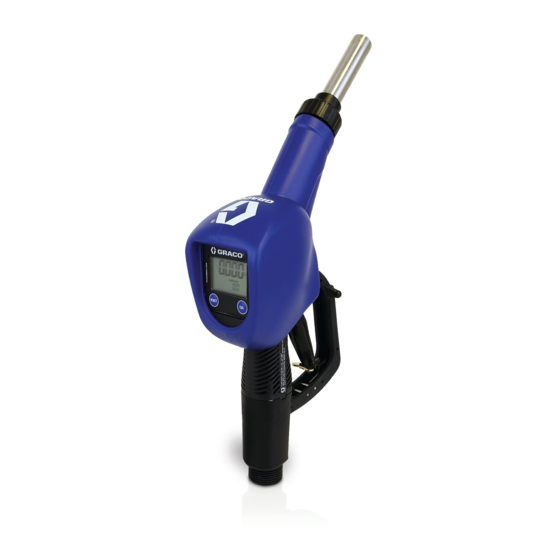
METERED AUTOMATIC SHUT-OFF NOZZLE
FOR DIESEL EXHAUST FLUID (DEF) (ISO 22241)
NOT APPROVED FOR USE IN EXPLOSIVE
ATMOSPHERES OR HAZARDOUS LOCATIONS
MODEL 127650
MAX WPR 345 kPa (3.4 bar) (50 psi)
Important Safety Instructions
Read all warnings and instructions in this manual.
Save these instructions
333469E
EN • FR • ES
Advertisement
Chapters
Table of Contents

Related Manuals for Graco 127650


Summary of Contents for Graco 127650
- Page 1 EN • FR • ES FOR DIESEL EXHAUST FLUID (DEF) (ISO 22241) NOT APPROVED FOR USE IN EXPLOSIVE ATMOSPHERES OR HAZARDOUS LOCATIONS MODEL 127650 MAX WPR 345 kPa (3.4 bar) (50 psi) Important Safety Instructions Read all warnings and instructions in this manual.
- Page 2 INDEX GENERAL WARNINGS FIRST AID RULES WARNINGS BECOMING ACQUAINTED WITH THE DEF DISPENSING NOZZLE WITH METER INTENDED USE TECHNICAL DATA INSTALLATION MODES OF OPERATION MECHANICAL CHARACTERISTICS ELECTRONIC CHARACTERISTICS PREVENTION MISFILLING (optional) PRELIMINARY CHECK INITIAL START UP USER BUTTONS BATTERY HOUSING DAILY USE DISPENSING IN NORMAL MODE J1.1...
- Page 3 It should remain available to end users and specialist vation installation and maintenance technicians for consultation at any time. Reproduction All reproduction rights are reserved by Graco Inc. The text cannot be reprinted without written permission rights B FIRST AID RULES Contact with the...
- Page 4 WARNINGS The following warnings are for the setup, use, grounding, and repair of this equipment. The exclamation point symbol alerts you to a general warning and the hazard symbols refer to procedure-specific risks. When these symbols appear in the body of this manual or on warn- ing labels, refer back to these Warnings.
- Page 5 Prolonged contact with the treated product may cause skin irritation: always wear protec- tive gloves during dispensing Personal Wear appropriate protec- This equipment includes but is not limited to: Protective tive equipment when in Protective eyewear, safety shoes, close-fittin Equipment the work area to help pre- clothing and hearing protection.
- Page 6 D TECHNICAL DATA 127650 15 l/min 45 l/min 0.9 bar 1” GAS 20 mm 3.5 bar 0.8 Kg 4 gpm 12 gpm 13 psi 1” BSP .787 in 50 psi 1.8 lb The wetted materials used in this device are : NOTE stainless steel, plastic and rubber suitable for AdBlue.
- Page 7 F MODES OF OPERATION F1 MECHANICAL CHARACTERISTICS FOREWORD The main feature of these nozzles is that they are easy to use. Two operating modes are available: Dispense by operating the nozzle lever. To interrupt dis- ASSISTED MODE pensing manually, release the lever. Use the opening lever lock device for automatic dispens- AUTOMATIC MODE ing.
- Page 8 F3 PREVENTION MISFILLING (optional) PREMISE Refuelling with the nozzle equipped with “magnet switch” is only possible in combination with the “magnet adapter” , so misfuelling into tanks is made impossible OPERATION The “magnet switch” is a fi ed magnetic field within the filler necks of the nozzle.
- Page 9 G PRELIMINARY CHECK NOTICE Check the correct operation of the lock device, ac- cording to the following procedure: 1 Take a graduated receptacle with a capacity of 20 litres (5 gal) 2 Begin dispensing into the receptacle, setting the lever in the minimum fl w position, until the receptacle is full.
- Page 10 H INITIAL START UP FOREWORD Only start dispensing after making sure that assembly and installation have been correctly performed. WARNING TOXIC FLUID OR FUMES HAZARD The faulty operation of this device could cause the spill of liquids that are hazardous for people and the envi- ronment.
- Page 11 I2 BATTERY HOUSING FIRE AND EXPLOSION HAZARD WARNING Battery replacement may create a static discharge which has potential to ignite an explosive atmo- sphere. Always replace batteries in a non-explosive atmosphere (non-hazardous) location. NOTICE The meter is powered by two 1.5V standard type batteries (size AAA).
- Page 12 J1.1 PARTIAL RESET (NORMAL MODE) The partial register can be reset by pressing the reset key when the meter is in standby, meaning when the display screen shows the word “TOTAL”. After pressing the reset key, during reset, the display screen first of all shows all the lit-up digits and then all the digits that are not lit up.
- Page 13 NOTE The flow rate is measured with reference to the unit of measurement of the Partial. For this reason, in case of the unit of measurement of the Partial and Total being different, as in the example shown below, it should be remembered that the indicated flow rate relates to the unit of measurement of the partial.
- Page 14 K CALIBRATION K1 WHY CALIBRATE? NOTICE When working in extreme operating or flow conditions, (close to minimum or maximum acceptable range values), it may be a good idea to calibrate in the field, in the real conditions in which the meter has to work.. K2 DEFINITIONS CALIBRATION FAC- Multiplication factor applied by the system to the electrical pulses received, to...
- Page 15 K4.1 DISPLAY OF CURRENT CALIBRATION FACTOR AND RESTORING FACTORY FACTOR. By pressing the CAL key while the meter is in Standby, the display page appears showing the current calibration factor used. If no calibration has ever been performed, or the factory setting has been restored after previous calibrations, the following display page will appear: The word “Fact”...
- Page 16 K 4.2.1 IN-FIELD CALIBRATION PROCEDURE ACTION DISPLAY NONE NEXT in Standby LONG CAL key keying The NEXT enters calibration mode, shows <<CAL>> and displays the calibration factor in use instead of partial. The words “Fact” and “USER” indicate which of the two factors (factory or user) is currently in use.
- Page 17 NO OPERATION At the end of the calculation, the new USER K FACTOR is shown for NOTICE a few seconds, after which the restart cycle is repeated to finall achieve standby condition. From now on, the indicated factor will become the calibration factor used by the NEXT and will continue to remain such even after a battery change NO OPERATION...
- Page 18 NO OPERATION At the end of the calculation, the new USER K FACTOR is shown for NOTICE a few seconds, after which the restart cycle is repeated to finall achieve standby condition. From now on, the indicated factor will become the calibration factor used by the NEXT and will continue to remain such even after a battery change NO OPERATION...
- Page 19 M MAINTENANCE Use 2x1.5 V alkaline batteries size AAA BATTERY REPLACEMENT FIRE AND EXPLOSION HAZARD WARNING Battery replacement may create a static discharge which has potential to ignite an explosive atmo- sphere. Always replace batteries in a non-explosive atmosphere (non-hazardous) location. The meter features two low-battery alarm levels: When the battery charge falls below the first level on the LCD, the fi ed battery symbol appears.
- Page 20 N MALFUNCTIONS N1 MECHANICAL MALFUNCTIONS WARNING TOXIC FLUID OR FUMES HAZARD Correct and regular maintenance of the nozzle and of the system to which it is connected prevents malfunctions and possible accidental and possible accidental spills of hazardous liquids. FOREWORD THE POSSIBLE CAUSES OF MALFUNCTION ARE MAINLY ATTRIBUT- ABLE TO THREE FACTORS: NOZZLE DIRTY IN INNER HOLE OF LIP AT END OF SPOUT...
- Page 21 O TECHNICAL DATA Measurement system TURBINE Flow Rate (Range) 15 - 45 (Litres/minute) - 4-12 gpm Operating pressure (Max) 3.5 (Bar) - 50 psi Storage temperature (Range) -20 - + 70 (°C) -4 - + 158 (°F) Storage humidity (Max) 95 (% RU) -10 - + 50 (°C) Operating temperature (Range)
- Page 22 Q DIMENSIONS 3/4” HOSE M0303...
- Page 23 ISO 9001 Registered DEF METERED NOZZLE Model Modèle, Modell, Modello, , Modelo, Malli, Mudel, Modelis, Mudell, , Samhail 127650 Part Bestelnr., Type, Teil, Codice, Del, , Peça, Referencia, Osa, Souást, Részegység, Daa, Dalis, Cz, Taqsima, as, , Páirt, Parte Complies With The EC Directives Voldoet aan de EG-richtlijnen, Conforme aux directives CE, Entspricht den EG-Richtlinien, Conforme alle direttive CE, Overholder EF-direktiverne, ...
- Page 24 This warranty is conditioned upon the prepaid return of the equipment claimed to be defective to an authorized Graco distributor for verific tion of the claimed defect. If the claimed defect is verifie , Graco will repair or replace free of charge any defective parts.
- Page 25 Cette page est intentionnellement laissée en blanc.
-
Page 26: Table Of Contents
TABLE DES MATIERES CONSIGNES GENERALES NORMES DE SECOURS ATTENTIONS CONNAITRE LE FED PISTOLET DE DISTRIBUTION AVEC COMPTEUR INTENDED USE CARACTÉRISTIQUES TECHNIQUES INSTALLATION MODES OF OPERATION CARACTÉRISTIQUES MÉCANIQUES CARACTÉRISTIQUES ÉLECTRONIQUES F..3 MISFILLING (option) VÉRIFICATIONS PRÉALABLES PREMIÈRE MISE EN MARCHE PRÉSENTATION TOUCHES UTILISATEUR SIÈGE DES PILES UTILISATION QUOTIDIENNE DISTRIBUTION EN MODALITÉ... -
Page 27: Aconsignes Generales
à du manuel l’installation et à l’entretien doivent pouvoir le consulter en tout moment. Droits de Tous les droits de reproduction sont réservés par Graco Inc. Le texte ne peut être reproduit sans l'autorisation reproduction écrite NORMES DE SECOURS Contact avec Pour les problèmes dérivant du produit traité... -
Page 28: B1 Attentions
ATTENTIONS Les avertissements suivants sont relatifs à la configu ation, l'utilisation, la mise à la terre et à la réparation de cet appareil. Le symbole du point d'exclamation signale un avertissement général et les symboles de danger se réfèrent aux risques spé- cifiques de procédure. - Page 29 MAUVAISE Une mauvaise utilisa- Ne pas faire fonctionner l'unité lorsque UTILISA- tion peut provoquer vous êtes fatigués ou sous l'influen e de TION DE des blessures graves ou drogues ou d'alcool. L'APPAREIL la mort. Ne pas dépasser la pression d’exercice maximum ou la température de fonc- tionnement du composant de système ayant la valeur nominale la plus basse.
-
Page 30: Cconnaitre Le Fed Pistolet De Distribution Avec Compteur
Le contact prolongé avec le produit traité peut causer des irritations à la peau : toujours utiliser des gants de protection pendant les opérations de distribu- tion. Équipe- Porter un équipement Ce équipement comprenne mais n'est ment de de protection indivi- pas limité... -
Page 31: Dcaractéristiques Techniques
CARACTÉRISTIQUES TECHNIQUES 127650 15 l/min 45 l/min 0.9 bar 1” GAS 20 mm 3.5 bar 0.8 Kg 4 gpm 12 gpm 13 psi 1” BSP .787 in 50 psi 1.8 lb Les matériaux en contact avec le fluide utilisés REMARQUE : dans cet appareil sont : acier inoxydable, plastique et caoutchouc adé-... -
Page 32: Fmodes Of Operation
MODES OF OPERATION F.1 CARACTÉRISTIQUES MÉCANIQUES REMARQUE La simplicité d’utilisation est la principale caractéristi- que de ces pistolets. Les deux modalités d’utilisation sont les suivantes: Distribuer en actionnant le levier du pistolet. Pour interrompre manuellement la distribution, relâcher le MODALITÉ levier. -
Page 33: Misfilling (Option)
F..3 MISFILLING (option) Avant-propos Pour avoir la certitude de ne pas distribuer dans des réservoirs un liquide ne pouvant le recevoir, il faut acheter des pistolets pourvus de « Magnet switch » à utiliser avec le « MAGNET ADAPTOR ». Opération Le «... -
Page 34: Gvérifications Préalables
VÉRIFICATIONS PRÉALABLES AVIS Contrôler le bon fonctionnement du dispositif de blo- cage en suivant la procédure suivante : 1 Se munir d’un récipient gradué d’une capacité de 20 litres (5 galons) 2 Procéder à la distribution dans le récipient et le rem- plir avec le levier dans la position de débit minimum. -
Page 35: Hpremière Mise En Marche
PREMIÈRE MISE EN MARCHE Avant-propos Commencer la distribution seulement après avoir vérifié que le montage et l’installation ont été effectués selon les règles de l’art. ATTENTION DANGER DE FLUIDE OU VAPEURS TOXIQUES LE FONCTIONNEMENT DÉFECTUEUX DE CE DISPOSITIF PEUT PROVOQUER L’ÉPANDAGE DE LIQUIDES DANGEREUX POUR LES PERSONNES ET L’ENVIRONNEMENT. -
Page 36: I.1 Touches Utilisateur
I.1 TOUCHES UTILISATEUR Avant-propos Volucompteur Numerique A Turbine est pourvu de deux boutons (reset et cal) qui eff ctuent individuellement deux fonctions principales et, ensemble, d’autres fonc- tions secondaires. Pour la touche la remise à zéro du registre de la quantité partielle et de la quan- tité... -
Page 37: Distribution En Modalité Normale (Normal Mode)
J.1 DISTRIBUTION EN MODALITÉ NORMALE (NORMAL MODE) Avant-propos Normal mode est la distribution standard. Pendant le comp- tage, on visualisera en même temps le “partiel distribué” et le “total zérotable” (reset total) REMARQUE Si on appuie accidentellement sur les touches pen- dant la distribution, il ne se produira rien stand by Quelques secondes après la fin de la distribution, sur le registre... -
Page 38: Mise À Zéro Du Reset Total (Total Zérotable)
J.1.2 MISE À ZÉRO DU RESET TOTAL (TOTAL ZÉROTABLE) L’opération de mise à zéro du Reset Total ne peut être effectuée qu’après une opération de mise à zéro du regis- tre du Partiel. En effet, il est possible de remettre à zéro le Reset Total en appuyant longtemps sur la touche RESET alors que l’écran affich le message RESET TOTAL comme dans la page-écran suivante:... -
Page 39: Distribution Avec Visualisation Instantanée Du Débit (Flow Rate Mode)
J.2 DISTRIBUTION AVEC VISUALISATION INSTANTANÉE DU DÉBIT (FLOW RATE MODE) Il est possible d’effectuer des distributions en affich t simultanément: 1 le partiel distribué 2 le Débit instantané (Flow Rate) dans [Unité du Par- tiel/minute] comme l’indique le schéma suivant: Procédure pour accéder à... -
Page 40: Ketalonnage
ETALONNAGE POURQUOI DOIT-ON CALIBRER? AVIS Quand on doit travailler dans des conditions proches aux conditions extrêmes d’utilisation ou de débit (avoisinant les valeurs minimum ou maximum de la plage admise), il pourrait être nécessaire d’effectuer un calibrage sur le champ dans les conditions réelles de travail de pistolet. -
Page 41: Retablissement Du "Factory K Factor
K.4.1 VISUALISATION “K FACTOR” ACTUEL ET RETABLISSEMENT DU “FACTORY K FACTOR” En appuyant longuement sur la touche « cal » pendant que l’appa- reil est en stand-by, on arrive à la page-écran qui montre le facteur d’étalonnage actuellement utilisé. Si on utilise Volucompteur Nume- rique A Turbine avec le “factory k factor”, la page représentée dans le schéma sera affiché... -
Page 42: Étalonnage Sur Place
K.4.2 ÉTALONNAGE SUR PLACE Avant-propos Cette procédure prévoit la distribution du fluide dans un réci- pient échantillon gradué dans les conditions de fonctionne- ment réelles (débit, viscosité, etc.) requérant la plus grande précision. REMARQUE Pour obtenir une étalonnage correcte du Volu- compteur Numerique A Turbine , il est essentiel de/d’: éliminer complètement l’air du circuit avant d’effectuer l’étalonnage... -
Page 43: Procédure Pour Effectuer
K 4.2.1 PROCÉDURE POUR EFFECTUER L’ÉTALONNAGE SUR PLACE ACTION AFFICHEUR NAUCUNE Volucompteur Numerique A Turbine Meter en stand by FRAPPE LONGUE DE LA TOUCHE CAL Le Volucompteur Numerique A Turbine Meter entre dans la modalité d’étalonnage, affiche ’indication « CAL » et le facteur d’ étalonnage en cours à... -
Page 44: 4.3 Modification Directe Du Facteur K
AUCUNE ACTION Au terme du calcul, le nouveau USER K FACTOR est affich AVIS pendant quelques secondes, puis le cycle de redémarrage se répète pour arriver enfin à la ondition de stand-by. ATTENTION: à partir de ce moment, le facteur indiqué sera le facteur d’étalonnage qu’utilisera le compteur. -
Page 45: Lconfiguration Des Compteurs
FRAPPE LONGUE DE LA TOUCHE RESET Meter est informé que la procédure d’étalonnage est fini . Avant RESET RESET RESET d’effectuer cette opération, veiller à ce que la valeur indiquée est égale à celle souhaitée. AUCUNE ACTION Au terme du calcul, le nouveau USER K FACTOR est affich AVIS pendant quelques secondes, puis le cycle de redémarrage se répète pour arriver enfin à... -
Page 46: Mentretien
ENTRETIEN Use 2x1.5 V alkaline batteries size AAA REMPLACEMENT DES BATTERIES ATTENTION DANGER D'INCENDIE – EXPLOSION Le remplacement de la batterie peut créer une décharge statique qui a le potentiel d'amorcer une atmosphère explosive. Toujours remplacer les batteries dans un environnement ayant une atmosphère non explosive (endroit non dange- reux). -
Page 47: Dysfonctionnements Mécaniques
Ne pas utiliser d’air comprime sur la turbine car AVIS elle pourrait s’endommager a cause de la rota- tion excessive. VÉRIFIER PÉRIODIQUEMENT LE BON FONC- TIONNEMENT DU DISPOSITIF D’ARRÊT AUTO- MATIQUE S’IL EXISTE, IL EST CONSEILLÉ DE VÉRIFIER PÉRIODI- QUEMENT LE FILTRE ET DE LE NETTOYER TOUS LES 1000 LITRES DE TRANSVASEMENT. -
Page 48: Odonnees Techniques
DONNEES TECHNIQUES Système de mesure TURBINE Débit (plage) 15 - 45 (litres/minute) - 4-12 gpm Pression de fonctionnement 3,5 (Bar) - 50 psi (Max) Température de stockage (plage) -20 - + 70 (°C) -4 - + 158 (°C) Humidité de stockage (Max) 95 % (UR) Température de fonctionnement -10 - + 50 (°C) -
Page 49: Pelimination
ELIMINATION Avant-propos En cas de démolition, ses parties doivent être confiées à de entreprises spécialisées en élimination et recyclage des déchets industriels et, en particulier: Elimination de L’ e mballage est constitué par du carton biodégradable qui peut l’emballage: être confié aux e treprises qui récupèrent la cellulose. Elimination des Les parties métalliques, aussi bien celles qui sont vernies que celles parties metalli-... -
Page 50: Rdéclaration De Conformité Ce
ISO 9001 Registered DEF METERED NOZZLE Model Modèle, Modell, Modello, , Modelo, Malli, Mudel, Modelis, Mudell, , Samhail 127650 Part Bestelnr., Type, Teil, Codice, Del, , Peça, Referencia, Osa, Souást, Részegység, Daa, Dalis, Cz, Taqsima, as, , Páirt, Parte Complies With The EC Directives Voldoet aan de EG-richtlijnen, Conforme aux directives CE, Entspricht den EG-Richtlinien, Conforme alle direttive CE, Overholder EF-direktiverne, ... -
Page 51: Garantie
CLUANT SANS AUCUNE LIMITATION LA GARANTIE DE COMMERCIABILITÉ OU DE ADAPTABILITÉ À UNE FINE PARTI- CULIÈRE. La seule et unique obligation de Graco et le recours exclusif de l' acheteur pour toute violation de garantie sont ceux établis ci-dessus. L'acheteur accepte qu'aucun autre recours (y compris, mais non limité à, dommages directs ou indirects pour manque à... - Page 52 Esta página se ha dejado en blanco intencionadamente...
- Page 53 INDICE ADVERTENCIAS GENERALES NORMAS DE PRIMEROS AUXILIOS B. 1 ADVERTENCIAS FAMILIARIZAR CON LA DEF PISTOLA DE SUMINISTRO CON CUENTALITROS USO PREVISTO DATOS TÉCNICOS INSTALACIÓN MODALIDAD DE UTILIZACIÓN CARACTERÍSTICAS MECÁNICAS CARACTERÍSTICAS ELECTRÓNICAS PREVENTION MISFILLING (optional) CONTROLES PREVIOS PRIMERA PUESTA EN MARCHA CÓMO SE PRESENTA PULSADORES USUARIO ALOJAMIENTO DE LAS BATERÍAS...
-
Page 54: Aadvertencias Generales
Derechos de Graco Inc. se reserva todos los derechos de reproducción. reproducción El texto no puede ser reproducido sin el permiso por escrito... -
Page 55: Advertencias
B. 1 ADVERTENCIAS Las siguientes advertencias se refieren a la instalación, el uso, la co- nexión a tierra, y la reparación de este equipo. El símbolo acompa- ñado de una exclamación le indica que se trata de una advertencia y el símbolo de peligro se refiere a un riesgo específico. - Page 56 UTILIZA- Una utilización inco- No utilice la unidad si está cansado CIÓN IN- rrecta puede causar o bajo la influencia de drogas o alco- CORRECTA muerte o lesiones hol. DEL EQUI- graves No exceda la presión máxima de trabajo o la temperatura del compo- nente con menor valor nominal del sistema.
-
Page 57: Cfamiliarizar Con La Def Pistola De Suministro Con Cuentalitros
El contacto prolongado con el producto puede causar irritación de la piel: utilice siempre guantes de protección durante el suministro. Equipo de Utilice el equipo de Este equipo incluye pero no se limita Protección protección adecuado Personal en el área de trabajo Gafas de protección, calzado de se- para prevenir lesio- guridad, ropa ceñida y protección... -
Page 58: Datos Técnicos
DATOS TÉCNICOS 127650 15 l/min 45 l/min 0.9 bar 1” GAS 20 mm 3.5 bar 0.8 Kg 4 gpm 12 gpm 13 psi 1” BSP .787 in 50 psi 1.8 lb Los materiales mojados utilizados en este dispo- NOTA sitivo son: acero inoxidable, plástico y caucho adecuados... -
Page 59: Fmodalidad De Utilización
MODALIDAD DE UTILIZACIÓN F.1 CARACTERÍSTICAS MECÁNICAS Premisa Estas pistolas se caracterizan principalmente por su fácil utilización. Son dos las modalidades de utilización: 1 MODALIDAD Efectuar el suministro accionando la palanca de la ASISTIDA pistola. Para interrumpir el suministro manualmente, soltar la palanca. 2 ODALIDAD AU- Utilizar el dispositivo de bloqueo de la palanca en apertura TOMÁTICA... -
Page 60: F3 Prevention Misfilling (Optional)
F3 PREVENTION MISFILLING (optional) Premisa Es posible tener la seguridad de no suministrar en de- pósitos no aptos para contener el líquido que se está suministrando si se opta por adquirir pistolas dotadas de “Magnet switch”, a utilizar con el “MAGNET ADAP- TOR”... -
Page 61: Gcontroles Previos
CONTROLES PREVIOS AVISO Controlar el funcionamiento correcto del dispo- sitivo de bloqueo utilizando el siguiente procedi- miento: Tomar un recipiente graduado, con una capacidad de 20 litros (5 gal). Iniciar el suministro en el recipiente, colocando la pa- lanca en la posición de flujo mínimo, hasta el llenado del mismo. -
Page 62: Hprimera Puesta En Marcha
PRIMERA PUESTA EN MARCHA Premisa Iniciar el suministro sólo después de haber com- probado que el montaje y la instalación hayan sido realizados correctamente. ATENCIÓN PELIGRO DE FLUIDOS O GASES TÓXICOS EL FUNCIONAMIENTO ANÓMALO DE DICHO DIS- POSITIVO PUEDE CAUSAR EL ESPARCIMIENTO DE LÍQUIDOS PELIGROSOS PARA LAS PERSONAS Y PARA EL AMBIENTE. -
Page 63: I.1 Pulsadores Usuario
I.1 PULSADORES USUARIO Premisa La pistola dispone de dos teclas (reset y cal) que permiten desarrollar, de forma individual, dos funciones principales y, de forma combinada, otras funciones secundarias. Para la tecla la puesta a cero de los registros del parcial y del total borrable RESET (reset total) para la tecla... -
Page 64: Suministro En Modalidad Normal (Normal Mode)
J.1 SUMINISTRO EN MODALIDAD NORMAL (NORMAL MODE) Premisa Normal mode es el suministro estándar. Durante el recuento, aparecen visualizados al mismo tiempo el “parcial suministra- do” y el “total borrable” (reset total). NOTA La pulsación accidental de las un mejor porvenirpara durante el suministro sin producir ningún efecto STAND BY Después de algunos segundos del final del suministro, en el... -
Page 65: Suministro Con Visualización De Caudal Instantáneo (Flow Rate Mode)
pulsar de nuevo la tecla Reset durante al menos 1 se- gundo 5 El display volverá a mostrar primero todos los seg- mentos encendidos y luego todos los segmentos apagados hasta llegar a la página en la que aparece visualizado el Reset Total puesto a cero J.2 SUMINISTRO CON VISUALIZACIÓN DE CAUDAL INSTANTÁNEO (FLOW RATE MODE) Podrán efectuarse suministros visualizando al mismo... -
Page 66: Puesta A Cero Del Parcial (Flow Rate Mode)
J.2.1 PUESTA A CERO DEL PARCIAL (FLOW RATE MODE) Para poner a cero el Registro del Parcial habrá que terminar el suministro, esperar a que la Unidad de Vi- sualización Remota indique un Flow Rate de 0.0, como se indica en la figu a, y luego pulsar brevemente la tecla RESET.. -
Page 67: Visualización Del "K Factor" Actual Yrestablecimiento Del "Factory K Factor
En modalidad de calibración, las indicaciones de parcial suministrado y acumula- tivo presentes en el display asumen distintos significados según la fase del pro- cedimiento de calibración. Durante la calibración, el meter no puede efectuar suministros normales. En modalidad de calibración los totales no se incrementan. NOTA El meter está... -
Page 68: Calibración In Situk
K.4.2 CALIBRACIÓN IN SITU FOREWORD Este procedimiento prevé el suministro del fluido en un reci- piente graduado de muestra, en las condiciones operativas rea- les (caudal, viscosidad, etc.) para las que se requiere la máxima precisión. NOTA Para obtener una calibración correcta es funda- mental: Eliminar por completo el aire de la instalación antes de efectuar la ca- libración... - Page 69 PULSACIÓN CORTA DE LA TECLA RESET El Meter es informado de que el suministro de calibración ha RESET terminado. Tener cuidado de que el suministro haya terminado correctamente antes de ejecutar esta acción. Para calibrar el Meter, el valor indicado por el totalizador parcial (ejemplo 9,800) deberá...
-
Page 70: Modificación Directa Del K Factor
K 4.3 MODIFICACIÓN DIRECTA DEL K FACTOR Este procedimiento es especialmente útil para corregir un “error medio” obteni- ble sobre la base de numerosos suministros efectuados. Si el SB32 M durante su utilización normal muestra un error porcentual medio, éste podrá corregirse apli- cando al factor de calibración actualmente utilizado una corrección del mismo porcentaje. - Page 71 ACCIÓN DISPLAY NINGUNA Unidad de Visualización Remota en modalidad normal, no en recue PULSACIÓN LARGA DE LA TECLA CAL La Unidad de Visualización Remota entra en la modalidad de calibración y es visualizado el factor de calibración utilizado en ese momento en lugar del parcial. Las inscripciones “Fact” o “USER”...
-
Page 72: Lconfiguración De Los Cuentalitros
CONFIGURACIÓN DE LOS CUENTALITROS Algunos modelos de cuentalitros disponen de un menú con el que el usuario po- drá seleccionar la unidad de medida principal, cuartos (qts), pintas (pts), litros (lit), galones (gal). La combinación entre las unidades de medida del registro del parcial y del registro de los totales es predefinida según la siguie te tabla: Unidad de Medida Unidad de Medida... -
Page 73: Mmantenimiento
MANTENIMIENTO Sustitución de las El meter se suministra con 2 baterías alcalinas (size baterías AAA) de 1,5 V. ATENCIÓN PELIGRO DE INCENDIO Y EXPLOSIÓN El reemplazo de la batería puede crear una des- carga eléctrica estática que podría infl mar una atmósfera explosiva. -
Page 74: Nanomalías De Funcionamiento
NO DESECHE LAS PILAS USADAS EN EL MEDIO AM- AVISO BIENTE. CONSULTE LAS NORMATIVAS LOCALES. NO UTILIZAR AIRE COMPRIMIDO SOBRE LA TURBINA PARA EVITAR QUE SE DAÑE A CAUSA DE UNA EXCESI- VA ROTACIÓN DESPUÉS DE LARGOS PERIODOS DE INUTILIZACIÓN, COMPROBAR EL FUNCIONAMIENTO CORRECTO DEL DISPOSITIVO DE PARADA AUTOMÁTICA SI SE HALLA PRESENTE, SE ACONSEJA CONTROLAR... -
Page 75: Odatos Técnicos
DATOS TÉCNICOS Sistema de medida TURBINA Velocidad de fluj (rango) 15 - 45 (litros/minuto) - 4-12 gpm Presión de funcionamiento (máx.) 3.5 (Bar) - 50 psi Temperatura de almacenamiento (rango) -20 - + 70 ( °C) -4 - + 158 ( °C) Humedad de almacenamiento (máx.) 95 (% RU) Temperatura de funcionamiento (rango) - Page 76 Q DIMENSIONES TOTALES 3/4” HOSE M0302...
-
Page 77: Rdeclaración De Conformidad Ce
ISO 9001 Registered DEF METERED NOZZLE Model Modèle, Modell, Modello, , Modelo, Malli, Mudel, Modelis, Mudell, , Samhail 127650 Part Bestelnr., Type, Teil, Codice, Del, , Peça, Referencia, Osa, Souást, Részegység, Daa, Dalis, Cz, Taqsima, as, , Páirt, Parte Complies With The EC Directives Voldoet aan de EG-richtlijnen, Conforme aux directives CE, Entspricht den EG-Richtlinien, Conforme alle direttive CE, Overholder EF-direktiverne, ... - Page 78 Esta página se ha dejado en blanco intencionadamente...
- Page 79 Esta página se ha dejado en blanco intencionadamente...
-
Page 80: Garantía
RO NO LIMITADO A, LA GARANTÍA DE COMERCIABILIDAD O DE ADECUACIÓN PARA UN FIN PARTICULAR. La única obligación de Graco y el único recurso del comprador frente a cualquier incumplimiento de la garantía serán los establecidos anteriormente. El comprador acepta que no dispondrá de ningún otro recurso (incluyendo, pero no limitado a, daños accidentales o consecuentes por ganancias pérdidas, ventas perdidas, daño a personas o propiedades o cual-...
Need help?
Do you have a question about the 127650 and is the answer not in the manual?
Questions and answers