Table of Contents
Advertisement
Quick Links
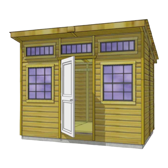
Thank you for purchasing a
12x8 Studio Garden Shed.
Please take the time to
identify all the parts prior to
assembly.
Safety Points and Other Considerations
Our products are built for use based on
proper installation on level ground and
normal residential use. Please follow the
instruction manual when building your
shed and retain the manual for future
maintenance purposes.
Customers are responsible for ensuring
a solid, level, well-draining site for
construction.
Please check with your local municipal
or county by-laws before ordering this
product to confirm it complies with
building codes.
In the event of a missing or broken piece, call the Outdoor Living Today Customer Support Line @ 1-888-658-1658 with-
in 30 days of the delivery of your purchase. It is our commitment to you to courier replacement parts, free of charge,
within 10 business days of this notification. Replacement parts will not be provided free of charge after the 30 day
grace period.
All structures purchased from Outdoor Living Today are covered for a period of one year for defects in manufacturing
and workmanship. Costs incurred for customer installations are not included.
Failure to use supplied parts included in this kit could result in poor product performance and may void your warranty.
Please contact Outdoor Living Today's Customer Toll Free Line if you plan to deviate from our written instructions.
1-888-658-1658
12x8 Studio Garden
Shed Assembly
- Snow load ratings vary by geographical location. If heavy or wet snowfall occurs, it
is advisable to sweep snow off roof frequently.
- If the product is elevated, any structural and building code requirements are solely
the customer's responsibility, and should be abided by.
- In areas with high or gusty wind conditions, it is advisable to install the structure
securely to the ground.
- Have a regular maintenance plan to ensure screws, doors, windows and parts are
tightly affixed.
Customer agrees to hold Outdoor Living Today and any Authorized
Dealers free of any liability for improper installation, maintenance and
repair.
www.outdoorlivingtoday.com
Page 1
Manual
sales@outdoorlivingtoday.com
Version #3
March 5th, 2019
Advertisement
Table of Contents

Related Manuals for OLT 12x8 Studio Garden


Summary of Contents for OLT 12x8 Studio Garden
- Page 1 12x8 Studio Garden March 5th, 2019 Shed Assembly Manual Thank you for purchasing a 12x8 Studio Garden Shed. Please take the time to identify all the parts prior to assembly. Safety Points and Other Considerations Our products are built for use based on proper installation on level ground and normal residential use.
-
Page 2: Table Of Contents
Thank you for purchasing our 12x8 Studio Garden Shed. Please take the time to identify all the parts prior to assembly. 1. Floor Section Parts List - Pages 2 and 3 Steps Floors 1-12 1A: 3 - 45 1/2” x 75” - Floor Joist Frames 1B: 6 - 1 1/2”... - Page 3 4. Trim Section Cont. Steps Soffits Rear 68-69 4E: 2 - 3/4” x 3 1/2” x 6 1/2” (Outside L/R Cap) 4F: 2 - 3/4” x 3 1/2” x 67” (Tongue & Groove) 4G: 2 - 3/4” x 2 3/4” x 67” (Tongue cut off - positioned against shed) 4H: 1 - 1/2”...
- Page 4 12X8 Studio Garden Shed HARDWARE PACKAGE Hardware Kit (Provided) x 442 S1 - 2 1/2” Screws x 71 S3 - 2” Screws S2 - 1 1/4” Screws x 356 x 475 N1 - 1 1/2” Finishing Nails BR1 - Square Drive Bit x 34 Y2 - 90°...
- Page 5 What Can I Do Before My Shed Arrives? Before starting your project become familiar with this assembly manual and determine if you can complete the project yourself or will require a professional contractor. Please note that certain counties and municipalities require building permits prior to installation. We recommend to all consumers that they check with their local county/municipality for these specifics prior to purchasing any of our products since this is your sole responsibility.
-
Page 6: - 45 1/2" X 75" - Floor Joist Frames
1. Floor Section Exploded view of all parts necessary to complete Floor Section. Identify all parts prior to starting. Note: Floor Footprint is 136 1/2” wide x 96” deep. Plywood Floor Plywood Floor Small - 3pcs. Large - 3pcs. (Part 1D) (Part 1E) Floor Joist FramesSmall -... - Page 7 You can find BR1 - Square Drive Bit for the screws in with the Hardware Kit Bag. Lay out 1A & 1C - Floor Joist Frames as illustrated. There are 3 larger and 3 smaller Frame Sections. The Footprint for the floor when attached together will be Attach each large and small floor joist 136 1/2”...
- Page 8 Foundations Note: The floor will be flipped over and the floor runners will sit on your foundation. It is important to note, that having a level foundation is critical. Choosing a foundation will vary between regions. Typical foundations can be concrete pads or patio stones positioned underneath the floor runners.
-
Page 9: Wall Section Steps
2. Wall Section Exploded view of all parts necessary to complete the Wall Section. Identify all parts prior to starting. Main Wall Side/Rear Top Plates - 6pcs. (Parts 2D & 2F) Rear Extender Walls - Rear Side Gable Walls 3pcs. (Part 2G) - 2pcs. -
Page 10: - 1 5/8" X 2 1/2" X 45 3/8" - Bottom Wall Plates
Ensure bottom plate You can find BR1 - is flush side-to-side Square Drive Bit for with wall studs the screws in with the Hardware Kit Bag. Bottom Wall Plate Parts Hardware Carefully lay 2B - Solid Wall Panels face 2B - Solid Wall Panels S1 - 2 1/2”... - Page 11 Optional - Caulking seams will help prevent moisture from entering at seam. Caulking not included in kit. Hardware Position side solid wall into place on plywood floor. Butt both vertical wall S1 - 2 1/2” Screws studs of side and rear walls together and attach with 3 - 2 1/2” Screws. Screw at x 3 total the bottom, middle and top of stud to secure properly.
- Page 12 Wall panel will sit flush with floor framing at side of shed. Do Not Attach Walls To Floor Until Step 35 Complete all side and rear wall attachments as per Step 17. Place Window Wall Panel in front and attach as per Step 17. 1-888-658-1658 www.outdoorlivingtoday.com sales@outdoorlivingtoday.com...
- Page 13 Top Plates should be flush with inside of wall framing. Parts Position 2D & 2F - Main Wall Side Top Plates on top of wall 2D - Main Wall Side Top Plates studs so they are flush on the inside with 2x3 wall stud. There are (3/4”...
-
Page 14: Rear Extender Walls - Rectangular
Protective cleat Cleat protects overhanging siding on upper walls from damage. Please remove before installing. Parts (Steps 23 - 24) Hardware (Steps 23 - 24) Place 2G - Rear Extender Walls on rear 2G - Rear Extender Walls S1 - 2 1/2” Screws wall plate with bottom siding overlapping that of (2G - 45 1/2”... - Page 15 From the outside, siding of gable will overlap side wall. When aligned, secure gable with 5 - 2 1/2” Screws. On a ladder, push extender wall and gable wall together tight and then screw. Front Side Gable. Position bottom frame of 2I - Front Side Gable Wall onto side wall top plate. Align so gable wall and side wall 2x3’s are even.
- Page 16 Even Inside Parts Position 2L - Door Jambs against window wall vertical framing. 2L - Door Jambs Jamb should sit even with the thick bevel siding on the outside and even (3/4” x 3 1/2” x 80 1/4”) x 2 with framing on the inside.
- Page 17 Center Upper Window Wall (1) Front Upper Window Walls (2) Clamp Parts (Steps 31 - 33) Starting with a 2M - Upper Front Window Wall - Side, 2M - Upper Front Window Walls - Sides place on front main wall top plate in corner. Upper wall siding (2M - 48 1/2”...
- Page 18 Position and attach the remaining 2M - Upper Front Window Wall - Side on front main wall top plate in corner as per Step 31. Clamp frames together to keep frames tight. To complete, screw both outside upper window panels from underneath window wall framing with 3 - 2 1/2” Screws per panel. Parts Position 2J - Upper Wall Plates on upper front window 2J - Upper Wall Plates - 11°...
- Page 19 38” Hardware When all walls are attached together, check alignment with the floor. Bottom S1 - 2 1/2” Screws wall framing should sit flush with outside of floor framing. Adjust for best fit. x 36 total Confirm 38” wide door opening at top and bottom. When positioned correctly, fasten bottom wall plates to floor using 4 - 2 1/2”...
-
Page 20: Rafter And Roof Section Steps
3. Rafter and Roof Section 47” (short) 47” (short) 72” (long) Even sides and ends. Parts (Steps 37 - 38) Rafters need to be assembled before laying of roof. There will be 3A - Rafter Sections -Short 7 completed rafters when pieces are attached together. There are 4 pieces (1 1/2”... - Page 21 Rafter flush with inside of side gable wall framing. Front Rafter Overhang Spacer. (14 1/2” long) Parts Position Rafter on gable wall framing. Locate 3F - Rafter Overhang 3F - Rafter Overhang Spacer Spacer and place underneath front of rafter flush against upper wall plate (3F - 14 1/2”...
- Page 22 Longer overhang 1 1/4” Screws Parts To assist in rafter alignment, you will need to assemble 3D - Plywood Rafter Spacer Jig - Sides the Rafter Spacer Jig (3 pcs made with plywood). Align the (2 1/2” x 68 3/4”) x 2 center piece with the longer overhang of the side pieces as 3E - Plywood Rafter Spacer Jig - Center shown above.
-
Page 23: - 1 1/2" X 3 1/2" X 59 1/2" - Rafter Facia (11° Angle Cut On Ends)
Hardware Slide Rafter Spacer Jig down to the rear. attach a 90° Metal Bracket (S2 - 1 1/4” Screws) x 40 total to each side of rafter and to the rear wall top plate. Use 4 - 1 1/4” Screws (Y2 - 90°... - Page 24 Screw down Rafter Spacer Jig 2 1/2” Screws onto Rafters with 2 - 2 1/2” Screws per rafter assembly. Hardware S1 - 2 1/2” Screws x 14 total Do not attach Roof Shingles overhang Front Outside plywood. Panel to Rafters until Roof Panel.
- Page 25 Plywood even with end of rafter. Plywood sitting evenly on 1 - 2x4 rafter. Line up roof plywood sheathing of front and rear roof panels. Plywood should sit even at bottom of rafter and even on 1 - 2x4 rafter. Middle Front.
-
Page 26: Roof Panels
Rear Middle Roof Panel. Locate Rear Middle Roof Panel. Carefully slide panel up on rafters as per Steps 51-52. Have your helper carefully lift the front roof panel up (lift plywood and not shingles) and slide rear panel underneath bottom shingles until plywood sheathing butts up flush with rafter spacer. Locate remaining Outside Front and Rear Roof Panels. - Page 27 2 screw at bottom row of shingles only. Note: In Steps 56 - 59 it is important to do the filler shingles one row at a time, working up the roof Hardware Screw roof panels down into rafter with 2 - 2 1/2” screws (S1 - 2 1/2”...
- Page 28 Complete all remaining Filler Shingle attachments as per Steps 56-58. While on the roof, attach 3L - Front Roof Ridge Caps on front of roof panel to cover screws used to secure the last smaller filler shingles. Use 6 - 1 1/2” Finishing Nails to secure each cap.
- Page 29 1 1/2” gap at front and rear. Facia Nailing Strips (72” & 44” long). Parts Locate 3M & 3N - Roof/Facia Nailing Strips. Strips will attach 3M - Roof/Facia Nailing Strips to the bottom of plywood sheathing flush with edge as shown to the (3/4”...
- Page 30 Edge even with Slight end of rafter. recess. Tight Hardware Carefully lift one of the front soffit sections and position underneath N1 - 1 1/2” Finishing Nails rafters tight against soffit cap. Front edge of soffit (grooved edge) should not x 12 total extend past end of rafters.
- Page 31 Small Gap. Center Soffit Cap. Locate and position 4E - Rear Soffit Caps underneath rear rafter, tight against wall and aligned with rafter seam as per Step 64. Cap Tongue cut off- should not extend past end of rafters. Attach with (narrow pc.) 2 - 1 1/2”...
- Page 32 Covers gap. Parts Carefully lift one of the rear soffit sections and position underneath 4H - Rear Center Soffit Cap rafters tight against soffit cap. Front edge of soffit (grooved edge) should (1/2” x 3 1/2” x 4 1/2”) x 1 not extend past end of rafters.
- Page 33 Note: All Trim, Facia and Bottom Skirting pieces Side Facia will be positioned rough face out when installed. (11° cut ends). Front Facia. Parts (Steps 71 - 75) Locate 4L - Front/Rear Facia & 4M - Side Facia. Start 4L - Front/Rear Facia by positioning one front facia up against front end of rafters.
- Page 34 Even Rear Facia. Tight up against shingles. After aligning two side facias and first rear facia, attach as per Steps 71-73. Once again, do a dry run before attaching. Attach remaining rear and lower side facia as per Steps 71-74. Parts Hardware Attach 4N - Facia Detail Plates to cover...
- Page 35 Side Skirting. Parts (Steps 77 - 78) Attach 4O - Bottom Skirting around base of the shed. Skirting 4O - Side/Rear Bottom Skirting will hide floor framing. The side skirting pieces will meet together in (3/4” x 4 1/2” x 45 1/2”) x 7 the center.
- Page 36 Reminder: Orientation of Trim Pieces is important. Left/Right pieces are mirror images with rough side facing outward Filler Trims will get covered in Steps 81-84 with proper corner trim. Small gap between trims. Parts Hardware Position 4R - Filler Trim (they serve as nailing 4R - Filler Trim S2 - 1 1/4”...
- Page 37 Scarf joint cut. Bottom Front Side Wide Corner Trim (22° scarf cut) Bottom Front (narrow) caps Bottom Side (wide) Parts From the Left Corner Trim package, locate 4W - 4W - Bottom Front Narrow Corner Trim Bottom Front Narrow Corner Trim and 4X - Bottom Front with 22°...
- Page 38 Scarf joint cuts on top and bottom trims. Tight up against rafter facia. Trim covers wall seam. Parts Hardware Place 4AB - Top Side Trim first up 4AB - Top Side Trim N1 - 1 1/2” Finishing Nails against rafter facia and evenly spaced to with 22°...
- Page 39 Screw near bottom on both sides where door was shimmed. Not into threshold. Hardware With door leveled in opening, open door and secure casing to shed framing S1 - 2 1/2” Screws where you shimmed. Use 2 - 2 1/2” Screws on top and 3 - 2 1/2” Screws on x 8 total each side.
- Page 40 Screw into thick butt of siding. Parts (Steps 90 - 92) To reduce possible water from penetrating into the window cavity, 4AI - Large Window Inserts caulk gap on both sides of window opening prior to installing the (30 1/4”w x 35”h) x 2 4AI - Large Window Inserts.
- Page 41 Top trim is angle cut on both ends. Window frame sits in trim dado. Parts Position 4AK - Large Window Trims around window, 4AK - Large Window Trims doing a dry run first. Attach with 4 - 1 1/2” Finishing Nails per (1 Top piece - 36 1/4”...
- Page 42 Parts Hardware Position 4AL - Transom Window 4AL - Transom Window Trim N1 - 1 1/2” Finishing Nails Trim around window, doing a dry run first. (1 Top piece - 41” angle ends) x 2 x 24 total Attach with as per Step 94 with (2 Side pieces - 10 5/8”...
- Page 43 Congratulations on assembling your 12x8 Studio Garden Shed! Note: Our Sheds are shipped as unfinished products. If exposed to the elements, the western red cedar lumber will weather to a silvery-gray color. If you prefer to keep the cedar lumber looking closer to the original color, we suggest that you treat the wood with a good oil base wood stain.
Need help?
Do you have a question about the 12x8 Studio Garden and is the answer not in the manual?
Questions and answers