
Related Manuals for Danfoss Performer SM Series


Summary of Contents for Danfoss Performer SM Series
- Page 1 MAKING MODERN LIVING POSSIBLE performer® scroll compressors sM - sY - sZ - 50 / 60 Hz R-22 - R-407c - R-134a - R-404a - R-507a selection & application REFRIGERATION & guidelines AIR CONDITIONING...
-
Page 2: Table Of Contents
WiRing ............................ Motor voltage ..................................................Electrical connections ............................................Suggested wiring diagrams logic ....................................Danfoss MCI soft-start controller ....................................sYsteM design RecoMMendations ..............................Refrigerant charge limit and compressor protection ...................... Crankcase heater ..............................................Liquid line solenoid valve (LLSV) .................................. - Page 3 contents speciFic application RecoMMendations ........................Low ambient compressor operations ................................Low ambient operation and minimum pressure differential ............Low ambient start-up ..........................................Head pressure control under low ambient conditions .................. Crankcase heaters ............................................Low load operations ..............................................Brazed plate heat exchangers ......................................
-
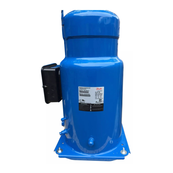
Page 4: Performer® Scroll Compression Principle
Danfoss Performer® scroll compressor, compression is performed by two scroll elements located above the motor (see adjacent figure). Suction gas enters the compressor at the suction connection, enters at the bottom of the motor housing and flows around the motor. -
Page 5: Compressor Model Designation
- 380* 7: 500/3/50 - 575/3/60 module M: rotolock B: 115/230V 9: 380/3/60 *For trio assemblies, please contact Danfoss connection details sM/sZ 084 - 090 - 100 sM/sZ 115 - 125 - 160 - Model sY/sZ 240 - 300 sY/sZ 380... -
Page 6: Technical Specifications
45 °F (dew point) Condensing temperature 130 °F 130 °F (dew point) Subcooling 15 °F 15 °F Superheat 20 °F 20 °F Subject to modification without prior notification For full data details and capacity tables refer to Online Datasheet Generator : www.danfoss.com/odsg... -
Page 7: 60-Hz Data
45 °F (dew point) Condensing temperature 130 °F 130 °F (dew point) Subcooling 15 °F 15 °F Superheat 20 °F 20 °F Subject to modification without prior notification For full data details and capacity tables refer to Online Datasheet Generator : www.danfoss.com/odsg... -
Page 8: Operating Envelopes
opeRating enVelopes application envelopes The figures below show the operat- shows the limit when the superheat is ing envelopes for SM / SY compres- F. Interpolate for superheat values at dew temperatures sors with refrigerant R-22 and for SZ between 20 F and 54 compressors with refrigerants R-407C, R-134a, R-404A and R-507A. - Page 9 opeRating enVelopes sZ 240 - 300 Condensing temp. limits R-134a S.H. = 54 SUPERHEAT S.H. = 20 Evaporating temperature [°F] sZ 084 to sZ 185 Condensing temp. limits R-404a / R-507a S.H. = 54 SUPERHEAT S.H. = 20 Evaporating temperature [°F] sZ 084 to sZ 185 Condensing temp.
-
Page 10: Application Envelopes At Mean Temperatures
opeRating enVelopes application envelopes at Refrigerant R-407C is a zeotropic mix- pressure lines. For a given cycle, the ture with a temperature glide in both MEAN point temperatures are typi- mean temperatures evaporator and condenser. Therefore, cally about 3.5° to 5.5°F lower than when discussing evaporating and DEW point temperatures. -
Page 11: Piping Connections
piping connections Brazed version Rotolock version Brazed Rotolock sleeve included suction and discharge Suction 1’’ 1/8 sM / sZ 084 Discharge 3/4’’ connections Suction 1’’ 1/8 sM / sZ 090 Discharge 3/4’’ Suction 1’’ 1/8 sM / sZ 100 Discharge 3/4’’... -
Page 12: Electrical Connections And Wiring
electRical connections and WiRing Motor voltage Performer® scroll compressors are 9 are for 60 Hz only, code 6 for 50 Hz available for five different motor only, and codes 4 and 7 for both 50 voltages. Motor voltage codes 3 and and 60 Hz. - Page 13 electRical connections and WiRing The 2 double power supply knockouts The protection rating of the terminal accommodate the following diameters: box is IP54 when correctly sized IP54- Ø 1”3/4 / Ø 44 mm (for 1”1/4 conduit) rated cable glands are used. Ø...
-
Page 14: Suggested Wiring Diagrams Logic
electRical connections and WiRing suggested wiring diagrams Compressor models SM / SZ 084 – 090 – 100 – 110 – 120 – 148 - 161 CONTROL CIRCUIT CONTROL CIRCUIT 180 s 180 s LLSV Wiring diagram with pump-down cycle Wiring diagram without pump-down cycle suggested wiring diagrams Compressor models SM / SZ 115 –... -
Page 15: Danfoss Mci Soft-Start Controller
460V / 3 / 60Hz) the inrush current costly demand charges from the can be reduced by use of a Danfoss resultant current spike. Upon starting, digitally-controlled MCI compressor the controller gradually increases the soft starter. - Page 16 electRical connections and WiRing Mci with By means of the built-in auxiliary no-load condition it can be selected contact (23-24) the bypass function is on the basis of the thermal current bypass contactor easily achieved (see wiring diagram (AC-1). below). (Contacts 13-14 are not applicable with No heat is generated by the MCI.
-
Page 17: System Design Recommendations
Danfoss (see page 34). The heater ambient conditions (temperature and must be energized for a minimum of wind). 12 hours before initial start-up (with Below 23°F ambient temperature with... -
Page 18: Liquid Receiver
sYsteM design RecoMMendations liquid receiver A liquid receiver is strongly recom- store the refrigerant charge during mended on split systems and remote off-cycles, greatly reducing the chance condenser systems with a total of refrigerant migration back to the refrigerant charge in excess of the compressor. -
Page 19: Refrigerant Charge Limits And Compressor Protection
Notes: The compressor must not be A DGT accessory is available from allowed to cycle on the discharge gas Danfoss: refer to page 35. thermostat. Continuous operation HP 1 Example 1 HP 2... -
Page 20: Motor Protection
140% of the compressor's rated Condensing Unit Selection Software, load current. A circuit breaker, on available from the Danfoss web site. the other hand, should be set at not The tripping current must never more than 125% of the compressor... -
Page 21: Phase Sequence And Reverse Rotation Protection
sYsteM design RecoMMendations • current value found in the data sheets; locked rotor protection: the MMT value appears as "A.Max" on protector must trip within 10 seconds the compressor nameplate. upon starting at a locked rotor Further requirements for the external current. -
Page 22: Voltage Unbalance
sYsteM design RecoMMendations Voltage imbalance Operating voltage limits are shown imbalance is 2%. Voltage imbalance in the table on page 12. The voltage causes high amperage on one or applied to the motor terminals must more phases, which in turn leads lie within these table limits during to overheating and possible motor both start-up and normal operations. -
Page 23: Internal Pressure Relief Valve
sYsteM design RecoMMendations internal pressure The SY/SZ240 to SY/SZ380 incorporate relief valve an internal relief valve set to open between the internal high and low pressure sides of the compressor when the pressure differential between the discharge and suction pressures surpasses 450 to 550 psi. -
Page 24: Specific Application Recommendations
For further information, please contact water valve does not open until Danfoss Technical Support. condensing pressure reaches satisfactory level. crankcase heaters Crankcase heaters strongly installations. -
Page 25: Low Load Operations
speciFic application RecoMMendations low load operations It is recommended that the unit be conditions may require frequent tested and monitored at minimum cycling of compressors. This can lead load and if possible during low to liquid refrigerant entering the ambient conditions as well. During compressor if the expansion valve low load conditions, implement the does not provide stable refrigerant... -
Page 26: Crankcase Heaters
speciFic application RecoMMendations most important issues for common ensure acceptable operating applications. Each application design , characteristics. though, should be thoroughly tested crankcase heaters Most reversible cycle units are crankcase heaters are mandatory located outdoors operate because of the high probability during conditions of low ambient of liquid migrating back to the temperature. -
Page 27: Sound And Vibration Management
Acoustic hoods are available of lower frequencies and is easier to from Danfoss as accessories. These quiet. hoods are easy to install quickly and Use of sound insulation materials on... -
Page 28: Installation
installation compressor handling Each Performer® scroll compressor is part of an installation, never use the delivered with two lift rings. Always lift rings on the compressor to lift the use these rings when lifting the entire installation. compressor. A spreader bar rated for Keep the compressor upright during the mass of the compressor is highly all handling maneuvers. -
Page 29: Removing Connections Shipping Plugs
installation Lock washer* Compressor SY-SZ 240 to 380 base plate HM 10 Bolt* Large Flat* ” 1.06 washer ” Steel mounting sleeve Rubber grommet Nut* *Not supplied with compressor Removing connections Before suction and discharge plugs are the compressor to the installation removed, the nitrogen holding charge in order to avoid moisture entering shipping plugs... -
Page 30: Filters Driers
Filter driers For new installations with SY / SZ compressors with mineral oil the compressors with polyolester oil, Danfoss DCL drier is recommended. Danfoss recommends using Danfoss The drier is should be oversized rather DML 100% molecular sieve solid core than undersized. -
Page 31: System Pressure Test
For specific applications not covered from the air. the compressor must herein, please contact Danfoss for not therefore be left open to the information. atmosphere for a long period of time. the compressor fitting plugs must only be removed just before brazing the compressor. -
Page 32: Vacuum Pump-Down And Moisture Removal
Always use the original oil specified by compressor suction line. See Bulletin Danfoss as shown on page 33. Use oil "Lubricants, filling in instructions for from new cans only. Danfoss Commercial Compressors". Top-up the oil while the compressor please note that sZ and sY use is running. -
Page 33: Accessories
6-7. Please refer to "Lubricant, Always use the original oil specified by filling in instructions for Danfoss Danfoss as shown below. Use oil from Commercial Compressors" for detailed new cans only. oil specifications and top-up method. -
Page 34: Crankcase Heaters
accessoRies crankcase heaters Accessory belt-type crankcase heaters against off-cycle refrigerant migration are designed to protect the compressor Optimum location area 1/2 h 1/3 h code no. description application pack size 7773109 Belt type crankcase heater, 65 W, 110 V, CE mark, UL SM/SZ084-161 7973001 Belt type crankcase heater, 65 W, 110 V, CE mark, UL... -
Page 35: Discharge Temperature Protection
accessoRies discharge temperature Discharge gas temperature must not attached to the discharge line within exceed 275°F. 6” of the compressor discharge port. protection The discharge gas thermostat acces- sory kit includes all components Discharge thermostat code required for installation as shown number: 7750009. -
Page 36: Ordering Information And Packaging
Performer® scroll compressors may The tables below list the code numbers be ordered from Danfoss in either for industrial packs. For ordering single industrial pack or in single packs. packs please replace the last digit with an "I". - Page 37 oRdeRing inFoRMation and pacKaging R-407c / R-134a sZ compressors in industrial-pack code no. compressor Motor design connections model protection 460/3/60 575/3/60 200-230/3/60 380/3/60 380-400/3/50 500/3/50 SZ084 Single Brazed SZ084-3VM SZ084-4VM SZ084-7VM SZ084-9VM SZ090 Single Brazed SZ090-3VM SZ090-4VM SZ090-7VM SZ090-9VM SZ100 Single Brazed SZ100-3VM...
-
Page 38: Packaging
oRdeRing inFoRMation and pacKaging packaging Multipack Single pack Multipack Single pack Gross Static Gross Length Width Height Length Width Height Compressor models Nbr* weight stacking weight pallets SM/SZ 084 44.9 37.4 29.0 18.5 14.6 23.5 SM/SZ 090 44.9 37.4 29.0 18.5 14.6 23.5... - Page 40 Danfoss A/S • www.danfoss.com Danfoss Inc., 7941 Corporate Drive, Baltimore, MD 21236 Tel. 410-931-8250, Fax 410-931-8256, www.danfoss.us USCO.PC.003.A1.22 Produced by Danfoss USCO- 06/2008...
Need help?
Do you have a question about the Performer SM Series and is the answer not in the manual?
Questions and answers