Table of Contents
Advertisement
Quick Links
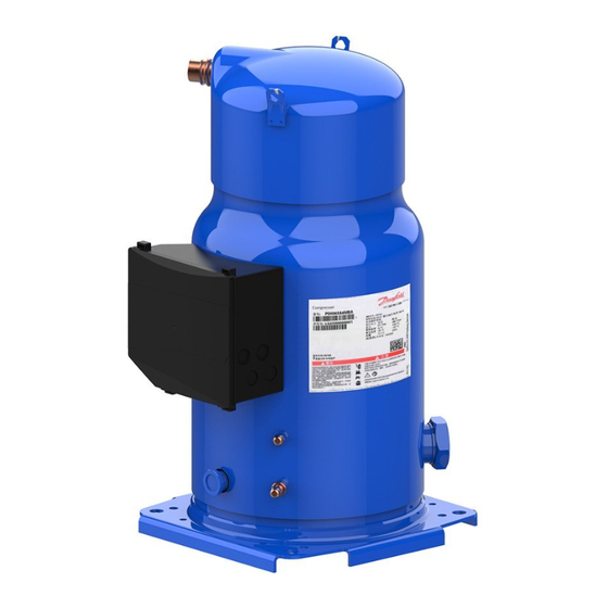
comPressors PsH019-023-026-030-034-039
1: Liquid Injection Valve
2: Liquid Injection Valve connection
3: Oil sight glass
Performer® PSH019-023-026-030-034-039 compressors are protected against overheating and
overloading by an internal safety motor protector. However, an external manual reset overload
protector is recommended for protecting the circuit against over-current. The compressors come
equipped with an electronic board OCS (Operating Control System) controlling liquid injection and
a liquid injection valve assembly.
70
65
60
SH 5K
55
50
45
40
35
30
25
20
15
-35
-30
-25
-20
The compressor must only be used for its
designed purpose(s) and within its scope of
application (refer to «operating limits»).
Consult Application guidelines and datasheet
available from cc.danfoss.com
1 – Introduction
These instructions pertain to the Performer® PSH
scroll compressors, models PSH019-023-026-
030-034-039, used for heat pump and air-condi-
tioning systems. They provide necessary infor-
mation regarding safety and proper usage of this
product.
2 – Handling and storage
• Handle the compressor with care. Use the
compressor lifting lugs and use appropriate
and safe lifting equipment.
• Avoid any shocks to the liquid Injection valve
during handling operations.
• Store and transport the compressor in an
upright position.
1
InstructIons PsH
2
A
1
B
3
A: Model number
B: Serial number
c: Refrigerant
Installation and servicing of the compressor by qualified personnel only. Follow
these instructions and sound refrigeration engineering practice relating to installation,
commissioning, maintenance and service.
-15
-10
-5
0
5
To (°C)
Under all circumstances,
the EN378 (or
applicable
regulation)
must be fulfilled.
• Store the compressor between -35°C and 50°C.
• Don't expose the compressor and the packa-
ging to rain or corrosive atmosphere.
3 – Safety measures before assembly
Never use the compressor in a flammable
atmosphere.
• The compressor ambient temperature may
not exceed 50°C during off-cycle.
• Mount the compressor on a horizontal flat
surface with less than 3° slope.
• Verify that the power supply corresponds to the
compressor motor characteristics (see nameplate).
• When installing PSH, use equipment specifi-
cally reserved for HFC refrigerants which was
FRCC.EI.020.A1.02 © Danfoss Commercial Compressors 02/12
D: Supply voltage, Starting current & Maximum operating current
e: Housing service pressure
F: Factory charged lubricant
10
15
20
25
30
The compressor is delivered under ni-
trogen gas pressure (between 0.3 and
other
0.7 bar) and hence cannot be connec-
local
safety
ted as is; refer to the «assembly» section
requirements
for further details.
CC
F1
F1
KA
KA
KA
KS
A1
T1
A3
180s
LPS
A2
HP
KS
LPS
DGT
KM
KA
KS
Wiring diagram without pump-down cycle
Legend:
Fuses...........................................................................................F1
Compressor.contactor. . ........................................................KM
Control.relay............................................................................KA
Safety.lock.out.relay. . ............................................................. KS
Optional.short.cycle.timer.(3.min).. . .............................. 180.s
High.pressure.safety.switch.................................................HP
Fused.disconnect....................................................................Q1
Compressor.motor.................................................................. M
Discharge.gas.temperature..............................................DGT
Safety.pressure.switch. . ....................................................... LPS
Control.circuit..........................................................................CC
Operating.Control.System................................................. OCS
The compressor must be
handled with caution in the
vertical position (maximum
offset from the vertical : 15°)
never used for CFC or HCFC refrigerants.
• Use clean and dehydrated refrigeration-grade
copper tubes and silver alloy brazing material.
• Use clean and dehydrated system components.
• The piping connected to the compressor must
be flexible in 3 dimensions to dampen vibrations.
4 – Assembly
• In parallel assemblies of PSH the compressor
requires a rigid mounting on the rails. Use the
pre-mounted rigid spacers.
• Slowly release the nitrogen holding charge
through the schrader port.
• Connect the compressor to the system as
soon as possible to avoid oil contamination
from ambient moisture.
D
E
F
L1
L2
L3
Q1
KM
T2
T3
OCS
M
Advertisement
Table of Contents

Related Manuals for Danfoss PSH Series


Summary of Contents for Danfoss PSH Series
- Page 1 • Store and transport the compressor in an • When installing PSH, use equipment specifi- soon as possible to avoid oil contamination upright position. cally reserved for HFC refrigerants which was from ambient moisture. FRCC.EI.020.A1.02 © Danfoss Commercial Compressors 02/12...
- Page 2 • Never release refrigerant to atmosphere. Danfoss can accept no responsibility for possible errors in catalogues, brochures and other printed material. Danfoss reserves the right to alter its products without notice. This also applies to products already on order provided that such alterations can be made without subsequential changes being necessary in specifications already agreed.
Need help?
Do you have a question about the PSH Series and is the answer not in the manual?
Questions and answers