Advertisement
Quick Links
Instructions
Danfoss scroll compressors
PSH051-064-077
3
2
5
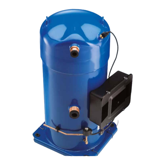
1: Discharge temperature sensor (supplied but
need to be connected)
2: Liquid Injection Valve (supplied)
3: Liquid Injection Valve connection 1/4" ODF
4: Surface Sump Heater (SSH) (supplied)
5: Rigid mounting spacer (supplied)
Danfoss scroll compressors PSH051-064-077 come equipped with an electronic board OCS (Opera-
ting Control System) protecting against phase loss/reversal, motor overheating, high current draw,
and giving extra features such as liquid injection, discharge temperature protection, envelope
monitoring, data storage, bus communication and crankcase heater control.
70
65
2.2
60
55
50
45
40
35
2.1
30
25
20
15
10
5
0
-5
-10
-15
-20
-25
-40
-35
-30
-25
-20
-15
Area1: Continuous running SH 5K to 20K
Area 2.1: 31 s maximum
The compressor must only be used for its
designed purpose(s) and within its scope of
application (refer to «operating limits»).
Consult Application guidelines and datasheet
available from cc.danfoss.com
1 – Introduction
These instructions pertain to the PSH scroll
compressors used for heat pump and air-
conditioning systems. They provide necessary
information regarding safety and proper usage
of this product.
2 – Handling and storage
• Handle the compressor with care. Use the
compressor lifting lugs and use appropriate
and safe lifting equipment.
• Avoid any shocks to the liquid Injection valve
during handling operations.
FRCC.PI.018.A3.02 - November 2014
1
4
A: Model number
B: Serial number
C: Refrigerant
Installation and servicing of the compressor by qualified personnel only. Follow
these instructions and sound refrigeration engineering practice relating to installation,
commissioning, maintenance and service.
1
2.3
3
-10
-5
0
5
10
15
20
T
(°C)
0
Area 2.2: 31 s maximum
Area 2.3: 3 min maximum
Under all circumstances,
the EN378 (or
applicable
regulation)
must be fulfilled.
• Store and transport the compressor in an
upright position.
• Store the compressor between -35°C and 51°C.
• Don't expose the compressor and the
packaging to rain or corrosive atmosphere.
3 – Safety measures before assembly
Never use the compressor in a flammable
atmosphere.
• The compressor ambient temperature may not
exceed 50°C during off-cycle.
• Mount the compressor on a horizontal flat
surface with less than 3° slope.
A
B
C
D: Supply voltage, Starting current & Maximum operating current
E: Housing service pressure
F: Factory charged lubricant
25
30
35
40
45
50
Area 1+2.3+3: Start / Restart map
Discharge pressure warning
The compressor is delivered under ni-
trogen gas pressure (between 0.3 and
other
0.7 bar) and hence cannot be connec-
local
safety
ted as is; refer to the «assembly» section
requirements
for further details.
CC
A1
LPS
A3
OCS
A2
KS
Legend:
Fuses ..........................................................................................F1
Compressor contactor .........................................................KM
Control relay ...........................................................................KA
Safety lock out relay .............................................................. KS
Optional short cycle timer (3 min) ............................... 180 s
High pressure safety switch.................................................HP
Control device .........................................................................TH
Fused disconnect ...................................................................Q1
Compressor motor ................................................................. M
Thermistor chain.......................................................................S
Safety pressure switch ........................................................ LPS
Control circuit ........................................................................CC
Operating Control System ............................................... OCS
The compressor must be
handled with caution in the
vertical position (maximum
offset from the vertical : 15°)
• Verify that the power supply corresponds to the
compressor motor characteristics (see nameplate).
• When
installing
PSH,
use
specifically reserved for HFC refrigerants which
was never used for CFC or HCFC refrigerants.
• Use clean and dehydrated refrigeration-grade
copper tubes and silver alloy brazing material.
• Use clean and dehydrated system components.
• The piping connected to the compressor must be
flexible in 3 dimensions to dampen vibrations.
4 – Assembly
• In parallel assemblies of PSH the compressor
© Copyright Danfoss | Commercial Compressors | 2014.11
D
E
F
S
equipment
Advertisement

Related Manuals for Danfoss PSH051-064-077


Summary of Contents for Danfoss PSH051-064-077
- Page 1 5: Rigid mounting spacer (supplied) Danfoss scroll compressors PSH051-064-077 come equipped with an electronic board OCS (Opera- ting Control System) protecting against phase loss/reversal, motor overheating, high current draw, and giving extra features such as liquid injection, discharge temperature protection, envelope monitoring, data storage, bus communication and crankcase heater control.
- Page 2 • Check suction superheat to reduce risk of Danfoss can accept no responsibility for possible errors in catalogues, brochures and other printed material. Danfoss reserves the right to alter its products without notice. This also applies to products already on order provided that such alterations can be made without subsequential changes being necessary in specifications already agreed.
Need help?
Do you have a question about the PSH051-064-077 and is the answer not in the manual?
Questions and answers