Advertisement
Quick Links
PROPER USE GUIDELINES
Cumulative Trauma Disorders can result from the prolonged use of manually powered hand tools. Hand tools are intended for occasional use and low volume
applications. A wide selection of powered application equipment for extended- - use, production operations is available.
The PRO- - CRIMPER III Hand Crimping Tool Assembly is a "Commercial"
grade tool and is designed primarily for field installation, repair, maintenance
work, or prototyping in industrial, commercial, or institutional applications.
Product crimped with this tool will meet the crimp height requirement for hand
tools in the appropriate 114 series specification, but may not comply with other
feature parameters of the specification. TE Connectivity offers a variety of tools
to satisfy your performance requirements. For additional information, contact
the Tooling Assistance Center at 1- - 800- - 722- - 1111.
TE Die
Product
Assembly
Assembly
Family}
Family}
Ultra--Fast FASTON*
58628--2
Straight Receptacle
Straight Receptacle
} Contact the Tooling Assistance Center or Product Information (at the numbers listed below) for specific receptacle part numbers.
1. INTRODUCTION
PRO--CRIMPER III Hand Crimping Tool Assembly
58628--1 consists of Die Assembly 58628--2 and
PRO--CRIMPER III Hand Crimping Tool Frame
354940--1. The tool is used to crimp the receptacles
onto the wire sizes listed in Figure 1.
Read these instructions thoroughly before crimping
any receptacles.
E2011 Tyco Electronics Corporation, a TE Connectivity Ltd. Company
All Rights Reserved
*Trademark
TE Connectivity, TE connectivity (logo), and TE (logo) are trademarks. Other logos, product and/or Company names may be trademarks of their respective owners.
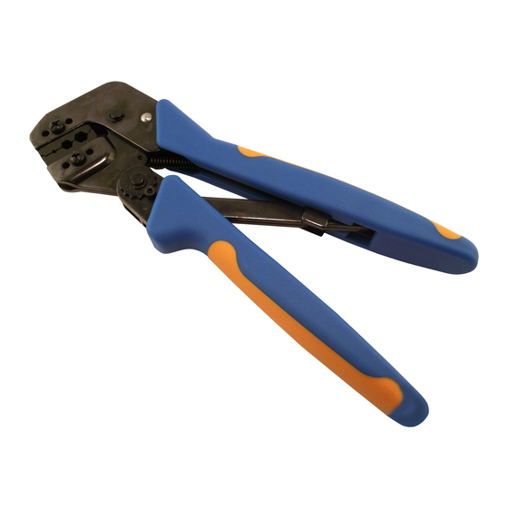
PRO- CRIMPER* III Hand Crimping
Tool Assembly 58628- 1 with
Die Assembly 58628- 2
Front of Tool
Die Assembly
Moving Jaw
Ratchet Adjustment
Wheel
Size
Size
(AWG)
110 and 125
Standard
26--22
2.54 [.100]
22--18
3.05 [.120]
16--14
—
Figure 1
TOOLING ASSISTANCE CENTER 1--800--722--1111
PRODUCT INFORMATION 1--800--522--6752
Stationary Jaw
Pivot Pin
Wire
Insulation Diameter (Max) (mm [in.])
for Receptacle Series Size
187 and 250
Large
Standard
—
—
5.84 [.230]
3.43 [.135]
6.60 [.260]
4.06 [.160]
If these instructions are revised, reasons for revison
will be listed in Section 9, REVISION SUMMARY.
Dimensions on this sheet are in millimeters [with
NOTE
inch equivalents provided in brackets]. Figures
i
are for identification only and are not drawn to
scale.
This controlled document is subject to change.
For latest revision and Regional Customer Service,
visit our website at www.te.com
Instruction Sheet
408- - 4452
29 APR 11 Rev B
Back of Tool
(Wire Side)
PRO- - CRIMPER III Hand
Crimping Tool Frame
354940- - 1 (408- - 9930)
Stationary
Handle
Moving
Handle
Strip Length
Strip Length
(mm [in.])
Large
—
7.14+0.41
5.84 [.230]
[.281+.016]
[ 281+ 016]
6.60 [.260]
1 of 4
LOC B
Advertisement

Related Manuals for TE Connectivity PRO- CRIMPER III


Summary of Contents for TE Connectivity PRO- CRIMPER III
- Page 1 PRODUCT INFORMATION 1--800--522--6752 For latest revision and Regional Customer Service, *Trademark visit our website at www.te.com LOC B TE Connectivity, TE connectivity (logo), and TE (logo) are trademarks. Other logos, product and/or Company names may be trademarks of their respective owners.
- Page 2 408- 4452 Tool Frame Die Retaining Pin (4 Places) Die Retaining Crimper Die Screws Crimping Chamber Wire Size Markings Anvil Die Figure 2 2. DESCRIPTION 5. To disassemble, open the tool handles, remove (Figures 1 and 2) the four die retaining pins and two die retaining The tool features a tool frame with a stationary jaw screws, and slide the dies out of the tool jaws.
- Page 3 408- 4452 Back of Tool Crimper Die Wire Crimping Chamber Receptacle Strip Length Anvil Die Figure 3 6. Inspect the crimped receptacle to ensure that good SAE 20 motor oil. If not, the tool must be the crimp is centered on the wire barrel and the adjusted according to Section 6, CRIMP HEIGHT wire is fully inserted.
- Page 4 408- 4452 6. RATCHET (Crimp Height) ADJUSTMENT 7.2. Visual Inspection (Figure 5) The crimping dies should be inspected on a regular 1. Remove the lockscrew from the ratchet basis to ensure that they have not become worn or adjustment wheel. damaged.