Advertisement
Quick Links
PROPER USE GUIDELINES
Cumulative Trauma Disorders can result from the prolonged use of manually powered hand tools. Hand tools are intended for occasional use
and low volume applications. A wide selection of powered application equipment for extended-use, production operations is available.
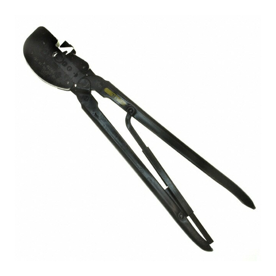
Stationary Crimping Dies
(Anvils)
Head
Tool Color Code: Yellow
Tool Dot Code: 1
TOOL
TYPE
PIDG* Vinyl and
Nylon Terminal and
Splice and
PLASTI-GRIP*
Terminal
PIDG Insulation
59239-4
Restring Nylon
59239-8
Terminal
525692
PIDG Radiation
Resistant
Terminal and Splice
Spare Wire Cap
328309
PIDG Vinyl and
Nylon Terminal and
59287-2
Splice and
PLASTI-GRIP
Terminal
‡ Heavy Duty
©2015 TE Connectivity family of companies
All Rights Reserved
*Trademark
TE Connectivity, TE connectivity (logo), and TE (logo) are trademarks. Other logos, product and/or Company names may be trademarks of their respective owners.
Heavy Head Hand Tools 59239-4,
59239-8, 59287-2, and 525692
Locator
Movable Crimping Dies
(Indenters)
PRODUCT
INSULATION COLOR
CODE
Yellow
Yellow w/ Black stripes
Yellow w/ 3 Yellow Stripes
Yellow w/ 3 Brown Stripes
Natural with Yellow Stripe
Natural with Yellow Stripe
Yellow
Yellow
Yellow w/ Black Stripe
PRODUCT INFORMATION 1-800-522-6752
Handles
Insulation Crimping
Adjustment Pin
TYPE
Solid or Stranded
Copper
Stranded Copper
Stranded Copper
Stranded Copper
Solid or Standed
Copper
Figure 1
This controlled document is subject to change.
For latest revision and Regional Customer Service,
visit our website at www.te.com
Instruction Sheet
408-1261
27 AUG 15 Rev K
Ratchet
WIRE
INSULATION
SIZE (AWG)
DIAMETER
(mm [in.])
12 - 10
5.84-6.35
[.230-.250]
16 - 14 ‡
2.41-5.08
12
[.095-.200]
3.02 - 5.08
10
[.119 - .200]
12 - 10
6.60 [.260] Max
16 - 14 ‡
12 - 10
5.33 [.210] Max
12 - 10
6.99-7.62
[.275-.300]
16 - 14 ‡
1 of 9
LOC B
Advertisement

Related Manuals for TE Connectivity 59239-4


Summary of Contents for TE Connectivity 59239-4
- Page 1 All Rights Reserved For latest revision and Regional Customer Service, *Trademark visit our website at www.te.com LOC B TE Connectivity, TE connectivity (logo), and TE (logo) are trademarks. Other logos, product and/or Company names may be trademarks of their respective owners.
- Page 2 1. INTRODUCTION The locator positions the product in the crimping chamber. The insulation crimping adjustment pin is Heavy Head Hand Tools (HHHT) 525692, 59239-4, used to regulate the height of the insulation crimp. 59239-8, and 59287-2 are designed to crimp the product listed in Figure 1 onto the wire also listed.
- Page 3 408-1261 4. Close the tool handles until the terminal is held firmly in place. DO NOT deform the terminal. 5. Insert a properly stripped wire into the terminal wire barrel until the end of the wire conductor(s) butts against the locator. DO NOT allow the wire insulation to enter the CAUTION terminal wire barrel.
- Page 4 408-1261 DO NOT allow wire insulation to enter the splice 5. Insert a properly stripped wire into the spare wire CAUTION wire barrel. cap until the wire conductor(s) bottoms. 6. Hold the wire in position, and complete the crimp by closing the tool handles until the ratchet releases.
- Page 5 408-1261 Figure 7 Rev K 5 of 9...
- Page 6 408-1261 Figure 8 Insert each insulation crimp adjustment pin into dependable and uniform terminations. Though position according to the following: recommendations call for at least one inspection a month, frequency of inspection depends on: Make sure that both insulation crimp adjustment CAUTION pins are in the same position.
- Page 7 408-1261 5.1. Daily Maintenance If gaging the crimping chamber is not required, NOTE inspect the die closure using an alternate 1. Immerse the tool (handles partially closed) in a procedure, i.e., the "Insulation Crimp Adjustment" reliable commercial degreasing compound to (see Section 4) and "Visual Inspection"...
- Page 8 408-1261 “W” = 6.35 +/-0.13 [.250 +/-.005] GAGE ELEMENT DIAMETER GAGE ELEMENT DIAMETER NO-GO NO-GO 4.293-4.300 [.1690-.1693] 4.442-4.445 [.1749-.1750] 1.626-1.633 [.0640-.0643] 2.131-2.134 [.0839-.0840] Figure 9 Detail A Detail B Inspection of Wire Barrel Inspection of Insulation Barrel Section of Crimping Chamber Section of Crimping Chamber Insulation Crimp Adjustment Pin...
- Page 9 Parts other than those listed should 7. REVISION SUMMARY be replaced by TE Connectivity to ensure quality and reliability. Order replacement parts through your • Updated document to corporate requirements representative, or call 1-800-526-5142, or send a •...
- Page 10 Mouser Electronics Authorized Distributor Click to View Pricing, Inventory, Delivery & Lifecycle Information: TE Connectivity 525692...
Need help?
Do you have a question about the 59239-4 and is the answer not in the manual?
Questions and answers