
Subscribe to Our Youtube Channel
Related Manuals for InHand IR300 Series


Summary of Contents for InHand IR300 Series
- Page 1 IR300 Series of Industrial Routers Quick Installation Manual Data Version: V 1.0—2020.6...
-
Page 2: Table Of Contents
Directory Overview ................................ 1 I. Packing list ..............................1 II.Panel Introduction and Structural Size......................2 2.1 Panel Introduction ..........................2 2.2 Structural Size ..........................3 III. Installation of Wireless Routers ........................ 3 3.1 Slippery Course Installation and Disassembly ................. 3 3.1.1 Slippery Course Installation .................... -
Page 3: Overview
Overview This manual is for the installation and operation of IR300 series routers of InHand Network Company. InHand makes every effort to provide accurate information in this manual, but InHand does not guarantee that there is no error in the manual. All statements, information and recommendations in this manual do not constitute any expressed or implied warranty. -
Page 4: Ii.panel Introduction And Structural Size
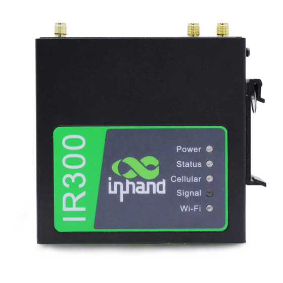
II.Panel Introduction and Structural Size 2.1 Panel Introduction Figure 2-1 Equipment Panel... -
Page 5: Structural Size
2.2 Structural Size Figure 2-2 Equipment Structure III. Installation of Wireless Routers Precautions for installation: ● Power requirements :12v DC (9~36 v DC), please pay attention to the power voltage levell; rated current is 0.2~0.22 A. ● environmental requirements: working temperature-20℃~70℃, storage temperature-40℃~85℃, relative humidity 5%~95%(no frosting), equipment surface may be high temperature, installation needs to consider the surrounding environment, should be installed in the restricted area ●... -
Page 6: Slippery Course Disassembly
Step 1: Select the installation location of the device and make sure there is enough space. Step 2: Tilt the equipment to the right 45°, so that the upper part of the DIN rail seat is stuck on the DIN rail, holding the lower end of the equipment, up slightly to rotate the equipment, the DIN rail seat can be stuck on the DIN rail. -
Page 7: Wall Hanging Installation And Disassembly
Push Push outwar Figure 3-1-2 Slippery Course Disassembly 3.2 Wall Hanging Installation and Disassembly 3.2.1 Wall Hanging Installation The steps are as follows: Step 1: Fix the hanging ear to both sides of the device with screws Step 2: Fix the hanging ear to the wall with screws. Figure .3-2-1 Wall Hanging Installation... -
Page 8: Wall Hanging Disassembly
3.2.2 Wall Hanging Disassembly Use one hand to hold the device and the other hand to remove the screws with screwdriver, remove device from the fixed position 3.3 SIM Card Installation IR300 support dual SIM card, hold down SIM pop-up button will pop up the card holder, load the SIM card Figure 3-3 SIM Card Installation 3.4 Antenna Installation Rotate the metal interface clockwise until the movable part can not be rotated, do not hold the black glue... - Page 9 Figure 3-4-a Glue Stick Antenna Installation Figure 3-4-b Chuck Antenna Installation...
-
Page 10: Power Installation
Note IR300 support dual antennas, ANT antenna and AUX antenna. The ANT antenna is the antenna which receives and transmits data, AUX antenna can only enhance the antenna signal degree and can not receieve and sent data, so it can’t be used alone. Generally, only use ANT antenna. 3.5 Power Installation The steps are as follows: Step 1: Remove power terminal from router;... -
Page 11: Quick Access To Internet
Attention In order to improve the anti-jamming ability of the router, the router must be grounded when it is used, and the ground wire is connected to the grounding stud of the router according to the actual use environment. IV. Quick access to Internet The device supports three ways of accessing the Internet: Wired, Cellular Dial-Up, WiFi note: when the device does not use Celluar Dial-up access, the "dial-up interface"... - Page 12 Figure 4-1 Ethernet Connection Step 2: Set the PC in the same network segment as the ip address of gateway device. Method 1: DHCP automatically get the address (Recommended) Method 2: Use fixed IP address, set the PC and gateway in the same address segment (DHCP Server for LAN2 Port is default enabled) Figure 4-1-2 Dynamic acquisition/manual Configuration PC only needs to configure the IP address to any value in:...
- Page 13 Step 3: Input the device default address 192.168.2.1 in the browser, enter the device Web page management (If the page indicates that the page is not secure, open hidden or advanced, select continue to go) Figure 4-1-3 Login WEB Page Management Step 4: Configuration WAN port, click on the navigation bar "Network >>WAN/LAN Switch",select WAN mode to configure IP address of Wan port, so that the device can access to the Internet..
- Page 14 Step 5: Three ways to assign address, dynamic DHCP( recommended), static address, ADSL dial (click application after configuration is completed) Figure 4-1-4-a Dynamic Ip Configure of WAN Figure 4-1-4-b Static Ip Configuration of WAN...
- Page 15 Figure 4-1-4-c ADSL Dial-up of WAN Step 6: Use the PING tool to verify your network connection. Figure 4-1-5 Ping Result Diagram...
-
Page 16: Sim Card Dial-Up
4.2 SIM Card Dial-Up Step 1: Insert the SIM card into the slot 1, /3 G/4G LTE the antenna to the ANT antenna column under the power condition of the equipment, connect the network wire to the PC and connect to the power supply. Attention SIM card must be replaced or plugged, power off restart to avoid data loss or equipment damage. -
Page 17: Wifi To Internet
Step 5: Click on the navigation bar "status >> network connection" to view the network status, showing the connected and assigned IP address and other status, indicating that the SIM card has successfully accessed the Internet. Figure 4-2-3 Dial-Up 4.3 WiFi to Internet Step 1: WiFi the antenna to connect the WLAN antenna column, the network wire to the PC and insert the power supply. - Page 18 Figure 4-3-1 SSID of AP Mode 2: STA mode means that station, device does not have the function of Internet access, it needs to connect to the AP device to provide bridges for the terminal equipment that can not connect to the AP, such as the PC device.
- Page 19 Figure 4-3-2- Reboot Device Step 4: Click on the navigation bar "Network >>WLAN Client ", click on the scan to select the target SSID, set encryption and password. Figure 4-3-4 Selected SSID...
- Page 20 Step 5: Click on the navigation bar "Network >>WAN (STA)", set WAN port IP parameter Three ways: dynamic address (recommended), static IP,ADSL dial. Figure 4-3-5-a Dynamic Acquisition WAN (STA) Address Figure 4-3-5- b Static IP Configuration of WAN (STA)
- Page 21 Figure 4-3-5- c ADSL Dial Configuration of WAN (STA) Step 6: Click on the navigation bar "Status >> Network Connection" to see the connection status, if connected and get the dynamic DHCP address, it means that the device is online. Figure 4-4-6 Schematic diagram of wireless networking results...
-
Page 22: Dm Cloud Management Platform
Make sure the device has been successfully accessed Internet, click on the "Service >> Device remote management platform" of the navigation menu to set up the access of DM Cloud Platform. (Follow-up version supports user experience plan, which can automatically access Inhand Cloud Platform and enjoy efficient and convenient service) Server address: the address of the Device Manager. -
Page 23: Platform Account Creation
5.2 Platform Account Creation Jump to the registration/login page through the link below for user registration. Link: https://iot.inhandnetworks.com. Figure 5-2 Account Registration/Login 5.3 Add Device to Platform Login to DM platform address https://iot.inhandnetworks.com, click on "Gateway >> Create" menu to add device. -
Page 24: Quick-Use Guidance
View Serial Number Method Click on the navigation bar "status" to view the device sequence and other basic information, or on the back of the device to view the serial number. Figure 4-5-3- b Serial Number Query VI. Quick-Use Guidance 6.1 Restore Factory Setting 6.1.1 Web Setting Login to the WEB page, click on the "System>>... -
Page 25: Hardware Restored
6.1.2 Hardware Restored Steps: step 1: find the RESET reset key on the device panel. Step 2: Hold down the RESET key for 10 seconds. Step 3: When you see the Status light on, release the RESET key; Step 4: After a few seconds when the Status lights go out, then re-hold the RESET key not release; Step 5: When you see the Status light flashing release the RESET key, indicating that the recovery factory settings are successful. -
Page 26: Log And Diagnostic Records
6.3 Log and Diagnostic Records log in to the Web page, click on the "Status >> Log" menu in the navigation tree to enter the "system log" interface. Click the corresponding button to complete the log and diagnostic records download. Figure 6-3 Diagnostic Log Function VII. - Page 27 2. release the Reset, Status destroy 3. immediately hold down Reset, then Status flicker, release the Reset button, restore factory success Note: Beijing Inhand Network Technology Co., Ltd. Signal values 0~10 Tel :86-10-84170010 Yellow Signal value 11~20 Fax :86-10-84170089...
Need help?
Do you have a question about the IR300 Series and is the answer not in the manual?
Questions and answers