Table of Contents
Advertisement
Quick Links
Advertisement
Table of Contents

Related Manuals for InHand IR900 Series


Summary of Contents for InHand IR900 Series
- Page 1 IR900 Series Industrial Router Quick Guide InHand Networks 2014 Jun 1 / 33...
-
Page 2: Table Of Contents
Contents 1. PRODUCT INFORMATION ................4 1.1 S ................4 TANDARD CCESSORIES 1.2 O ................4 PTIONAL CCESSORIES 2. PANEL & STRUCTURE ..................5 2.1 L ....................... 5 AYOUT 2.2 P ................5 HYSICAL IMENSIONS 3. INSTALLATION GUIDE ..................6 3.1 DIN R ................... - Page 3 5.1.4 Test the Connection ..............21 ............22 5.2 C ’ IP A HANGE AN NTERFACE DDRESS 6. DIAGNOSE THE IR900 ................... 24 6.1 V ................... 24 IEW THE ................. 25 6.2 D OWNLOAD THE 6.3 O .................. 26 PEN THE .................
-
Page 4: Product Information
1. Product Information The purpose of this guide to aid customers in installing and operating the 900 series Industrial Router, a cellular product of InHand Networks. Please make sure the product model and the accessories are included in the packaging. -
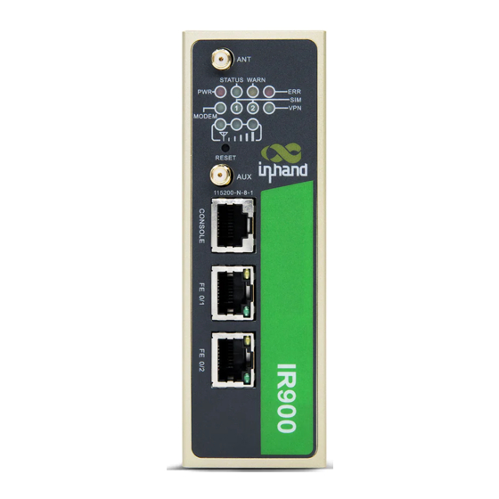
Page 5: Panel & Structure
2. Panel & structure 2.1 Layout IR900 series has a variety of port layouts and panel appearance, but all of the installation methods are the same. 2.2 Physical Dimensions Figure 2-2, Dimensions 5 / 33... -
Page 6: Installation Guide
3. Installation Guide 24 VDC (12 ~ 48VDC). Power Requirments: Operating Temperature: -25 ~ 70 °C Storage Temperature: -40 ~ 85 °C Humidity: 5 ~ 90% relative humidity (noncondensing) Avoid direct sunlight, and keep away from heat sources or areas with strong electromagnetic interference. -
Page 7: Din Rail Disassembly
3.1.2 DIN rail disassembly Removing the IR900 is opposite of mounting it: 1. Pull the bottom part of the router out until the bottom lip of the bracket unclips from the rail. This may take some force. 2. Lift the IR900 so that the rail seat clears the top part of the DIN rail. The router will now be free of the DIN rail. -
Page 8: Wall Mount Disassembly
well anchored. Figure 3-2-1-2 Wall mounting 3.2.2 Wall Mount disassembly To uninstall the device, hold it with one hand, while unscrewing it from the wall. 8 / 33... -
Page 9: Sim Card Installation
3.3 SIM Card Installation Before changing SIM cards, power off the device! 1. To open the SIM card slot press the small yellow button beside the SIM slot. 2. A small plastic SIM holder will pop out. 3. Put a SIM card into the holder. Micro or nano SIM cards will need an adapter. -
Page 10: Antenna Installation
3.4 Antenna Installation 1. To attach the antenna, first screw the antenna into its base. a. Do not turn it too tight and damage the rubber coating. 2. Attach the antenna by screwing it onto the SMA connector. 3. Check the letters on the base of the antenna: a. -
Page 11: Power Supply Installation
3.5 Power Supply Installation 1. Before proceeding, insert the power terminal into the DC power plug. 2. Loosen the lockdown screws. 3. Note which side of the terminal is positive and which side is negative. 4. Find the leads from the DC power source and insert the lead wires. 5. -
Page 12: Ethernet Connection
3.7 Ethernet Connection Plug one end of an Ethernet CAT5e cable into the FE 0/2 port. Plug the other end into a PC. Figure 3-7, Ethernet. 12 / 33... -
Page 13: Serial And Io Interface
3.8 Serial and IO Interface The serial, IO and relay interfaces are used to connect PLCs and other industrial devices. IR900 provide two serial interface modes: RS232 and RS485. To begin connecting the serial port, first obtain: A green elbow terminator A small flat-head screwdriver Light duty copper wire 1. -
Page 14: Access The Web Interface
Many users connect the lead wires into the wrong serial ports. If the PLC is not properly connected, try rewiring the serial port. 4. Access the Web Interface 4.1 Set the PC’s IP address Before starting, disconnect from any VPNs or proxies and temporarily disable the computers wireless interface. - Page 15 Click the Properties button to enter the window “Local Connection Properties.” Figure 4-1-3, Ethernet Status Select the text box “Internet Protocol Version 4 (TCP/IPv4),” and click Properties. Figure 4-1-4, IP Settings 15 / 33...
- Page 16 Set the IP address to 192.168.2.50 (or any IP from the range of 192.168.2.3 – 192.168.2.254) Set the subnet mask to 255.255.255.0 Set the gateway to 192.168.2.1 Press OK and exit all windows to save. Figure 4-1-5, IPv4 Settings Ping 192.168.2.1 to make sure the PC is connected. c.
-
Page 17: Log Into The Web Interface
4.2 Log into the Web interface. 1. To begin configuring the IR900, open your preferred browser. 2. Type 192.168.2.1 into the address bar and press enter. a. Username: b. Password: 123456 3. The web interface controls all the IG601’s features. Figure 4-2, Web login. - Page 18 Click on the drop-down menu and select English, Ingles, or 英语. Click the bottom-left button, Apply. Figure 4-3-2 18 / 33...
-
Page 19: Basic Configuration
5. Basic Configuration 5.1 Cellular Settings 5.1.1 Find the SIM settings Search for the SIM card’s settings in your favorite search engine. Save these settings for later. Many GSM cards will require an APN like ‘epc.t-mobile,’ with a blank username and password. -
Page 20: Enter The Cell Network Settings
5.1.2 Enter the Cell Network Settings. To enter the correct SIM settings: Open the web interface by typing 192.168.2.1 into the browser’s address bar, as shown in chapter 4. Navigate to Network >> Cellular on the left sidebar. ... -
Page 21: Check The Status
5.1.3 Check the Status • Make sure there is an IP on the Network >> Cellular >> Status tab. • Check that the ‘Status ’ is ‘Connected.’ Figure 5-1-3, Cell Status 5.1.4 Test the Connection Navigate to Tools >> Ping ... -
Page 22: Change An Interface Sip Address
Attach the correct antenna. Check the SIM card: o Is it in good standing? o Does it have a data plan? o Are the contacts too worn? Check the WAP name. Make sure the cell data plan is not over the data limit and in good standing. - Page 23 same subnet. Finally, type the new IP of the IR900’s LAV port into the browser’s address bar. In Tools >> Ping, ping 8.8.8.8 to test WAN connectivity. Figure 5-2-2 Sometimes users may forget the IP or there may be a problem with the interface configuration.
-
Page 24: Diagnose The Ir900
6. Diagnose the IR900 6.1 View the Log To view system logs, go to Administration >> Log. The logs are vital to diagnosing and fixing problems. Figure 6-1, Logs 24 / 33... -
Page 25: Download The Log File
6.2 Download the Log File To download the log files, navigate to Administration >> Log. Scroll down to the bottom of the page. Click Download Log File. Figure 6-2, Download Logs 25 / 33... -
Page 26: Open The Log File
6.3 Open the Log File The browser will download the log files to /<user>/Downloads Open the log files with Notepad++ or a comparable document editor. Windows Notepad will not open the log files properly. Figure 6-3, Open Logs 26 / 33... -
Page 27: Diagnose The Logs
6.4 Diagnose the Logs To view system logs, go to Administration >> Log. In this example, the cellular interface is trying to establish a connection over and over. The modem is constantly redialing. I must check the cell interface in Network >> Cellular. Figure 6-4-1, Diagnose logs. - Page 28 If the router continues searching for a cell connection, eventually the auto-recovery feature will cause a reboot. To prevent the router from constantly rebooting, either insert a SIM card or disable the interface. To disable the interface: Navigate to Network >> Dialup ...
-
Page 29: The Led Array
6.5 The LED Array When the router boots up or connects to a cellular network it will display codes on the LED array. Starting Up Successful Boot Dialing Successful Dialup Sucessful Reset Upgrading Figure 6-5, LED Array 29 / 33... - Page 30 Indicates a weak cell signal. Make sure the antenna is correct and the SMA connector is not loose. Normal operating cell signal. Excellent reception. 30 / 33...
-
Page 31: Restore The Default Configuration
7. Restore the Default Configuration 7.1 Software Restore To restore the device’s configuration to factory default: 1. Log into the web interface, as shown in chapter four. 2. Click Administration >> Config Management on the sidebar. 3. Click the Restore default configuration button. Figure 7-1-1, Web Restore. -
Page 32: The Pinhole Reset Button
7.2 The Pinhole RESET Button Follow these steps to restore the IR900 to factory default settings by using the pinhole “RESET” button: 1. Power off the router. 2. Turn on the router. 3. Within five seconds of powering up, press and hold the RESET button. 4. -
Page 33: Support
8. Support The IR900 enables admins to quickly deploy a secure, reliable network for their devices. Hopefully, this guide has helped get the IR900 into service. For technical support contact: support@inhandnetworks.com 33 / 33...
Need help?
Do you have a question about the IR900 Series and is the answer not in the manual?
Questions and answers