
Related Manuals for InHand InRouter900 Series


Summary of Contents for InHand InRouter900 Series
-
Page 1: User Manual
InRouter900 Series User Manual InHand Networks www.inhandnetworks.com Version: v3.2 December 2016... - Page 2 Preface Thanks for choosing InRouter900 series industrial routers! This user manual will guide you in detail on how to configure InRouter900. Readers This manual is mainly intended for the following engineers: Network planners On-site technical support and maintenance personnel ...
-
Page 3: Technical Support
2. Format Conventions on Graphic Interface Format Significance The content in angle brackets "<>" indicates button name, e.g. "click <> <OK> button.” The content in square brackets "[]" indicates window name, menu name or data sheet, e.g. “pop-up the [New User] window”. Multi-level menu is separated by "/". -
Page 4: Table Of Contents
Contents I. I 900 I OUTER NTRODUCTION ....................6 1.1 Overview ..........................6 1.2 Packing List......................... 6 1.3. Panel Introduction ......................8 1.4 Introductions to Status LED ....................9 II. E QUIPMENT NSTALLATION ....................... 9 2.1 DIN Rail Mounting and Disassembly ................10 2.1.1 DIN Rail Mounting .................... - Page 5 3.3.1 SLA ..........................32 3.3.2 Track Module ......................32 3.3.3 VRRP ......................... 33 3.3.4 Interface Backup ......................34 3.4 Routing ..........................35 3.4.1 Static Route ........................ 35 3.4.2 Dynamic Routing ....................... 35 3.4.3 Multicast Routing ....................... 38 3.5 Firewall ..........................39 3.5.1 Access Control (ACL) ....................
- Page 6 4.6.2 ADSL Dialup ......................61 New LAN ........................63 VRRP Typical Configuration Example ............... 64 Interface Backup Application Example ............... 66 4.10 Static Routing Application Example ............... 70 4.11 Dynamic Routing Application Example ..............72 4.12 Multicast Routing Application Example ..............75 4.13 Access Control Application Example .................
-
Page 7: Inrouter900 Introduction
I. InRouter900 Introduction 1.1 Overview IR900 is a new generation of 4G LTE VPN industrial router developed by InHand Networks. Integrating 4G LTE and various broadband WANs, IR900 provides uninterrupted access to internet. With the features of complete security and wireless service, IR900 can connect up to ten thousand devices, which can provide a high-speed data access for a real sense of equipment informatization. - Page 8 DIN-Rail Router fixation Power Terminal 2-pin green power terminal Cable 1.5m cable Antenna 3G/4G antenna Optional Accessories Accessories Quantity Description AC power cord AC power cord 12VDC power adapter Power Adapter Wi-Fi antenna Antenna Serial port cable Serial port cable...
-
Page 9: Panel Introduction
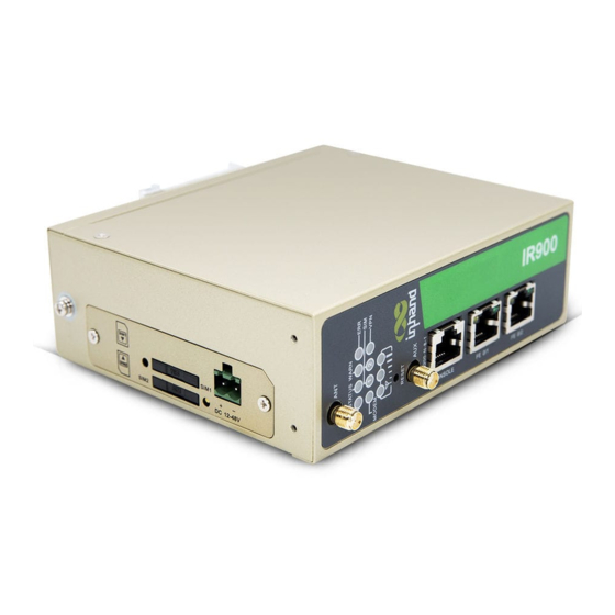
1.3. Panel Introduction Protective Grounding Stud SIM card seat SIM card seat popup key Power Port Antenna Port LED Indicator Light RESET Indicator Light CONSOLE Port 100M Ethernet Port IR900 series has a variety of panel appearances, but all of the installation methods are the same. The specific panel condition should be subject to the real object. -
Page 10: Introductions To Status Led
1.4 Introductions to Status LED Status Description: POWER STATUS WARN ERROR Description (Red) (Green) (Yellow) (Red) Powered On Blinking Powered on succeed Blinking Blinking Dialing Blinking Dialing succeed Blinking Blinking Blinking Upgrading Blinking Blinking Reset Succeed For the LED of two SIM card, the LED of SIM card 1 will be on during "Powered On" and "Powered on succeed"... -
Page 11: Din Rail Mounting And Disassembly
Environment requirement: working temperature -25℃~70℃, storage temperature -40℃~85℃, relative humidity 5%~95% (noncondensing). High temperature can be applied on equipment surface. During installation, surroundings should be taken into consideration and installation should be carried out within restricted area. Avoid direct sunlight, and keep away from heat sources or areas with strong electromagnetic interference. - Page 12 Fig. 2-1-2...
-
Page 13: Wall Mounting And Disassembly
2.2 Wall Mounting and Disassembly 2.2.1 Wall Mounting The specific steps are shown in below: Step 1: Select the installation location of the device, making sure there is enough space. Step 2: Use a screwdriver to attach the wall mounting plate to the back of the device as shown in Figure 2-2-1. - Page 14 black rubber lining. IR900 support dual antennas: ANT antenna and AUX antenna. ANT antenna is for data receiving and transmission; AUX antenna is for increasing signal strength, which cannot be used separately without ANT antenna. Normally, ANT antenna is used; AUX antenna is required when the signal is weak.
-
Page 15: Installation Of Power Supply And Protective Grounding
2.4 Installation of Power Supply and Protective Grounding Specific steps for power supply installation are shown below: Step 1: take out the terminal from the router and screw down the lock screw on terminal; Step 2: screw up the bolt after inserting power cable in terminal. Specific steps for protective grounding installation are shown below: Step 1: Remove the grounding nut. -
Page 16: Terminal Connection (Only Applicable To The Device With Industrial Interface)
2.5 Terminal Connection (only applicable to the device with industrial interface) Serial port and IO port are of terminal access, thus relevant wires should be connected with terminals before use. Serial port of device provides two interface modes: RS232 and RS485. Input end of IO port: IN indicates to digital quantity input end;... -
Page 17: Login Router
2.6 Login Router Firstly, IP address of PC should be changed to ensure it is within a same network segment as the device in the following two methods: automatic acquisition of IP address and static IP address. Proxy server (if any) should be cancelled for PC management settings. After setting the IP address of supervisory PC and ensuring there is no proxy server, the device can be logged in via web page. -
Page 18: Web Configuration
III. Web Configuration 3.1 Management The management includes 12 function modules: system, system time, management access, AAA, configuration management, SNMP, alarm, system log, system upgrade, reboot, network management platform and GPS locating information. 3.1.1 System Here, system and network state and system time of synchronizing device and PC can be checked and router WEB configuration interface language can be set as well as the name of mainframe of router can be customized. -
Page 19: Aaa
Super User can neither modify nor delete its username (adm); but the password can be changed. User right includes three levels: User right 1-11: only access to parameters check rather than configuration; User right 12-14: access to configure LAN IP, system time setting, basic configuration of firewall, virtual IP mapping table, system log, certificate application, access control, static routing, system upgrade and tool-ping detection. - Page 20 security and that permit remote user access. 2) Tacacs+ TCP protocol, mainly used for authentication, authorization and charging of access users and terminal users adopting PPP and VPDN. 3) LDAP LDAP, simple as a table, only requires username, command, and something else, which makes it very simple.
-
Page 21: Configuration Management
3.1.5 Configuration Management Here you can back up the configuration parameters, import the desired parameters configuration backup and reset the router. Table 3-1-4 Configuration Management Parameter Description Parameters Description Default Browse Choose the configuration file None Import Import configuration file to router startup-config None Backup running-config Backup running-config file to host. - Page 22 To configure SNMP in networking, NMS, a management program of SNMP, should be configured at the Manager. Meanwhile, Agent should be configured as well. Through SNMP: NMS could collect status information of devices whenever and wherever and achieve remote control of devices under management through Agent.
-
Page 23: Alarm
Table 3-1-7 SnmpTrap Configuration Parameter Description Parameters Description Default Host Address Fill in the NMS IP address None Security Fill in the groupname when use the SNMP v1/v2c; Fill in the None Name username when use the SNMP v3. Length :1-32 characters UDP Port Fill in UDP port, the default port range is 1-65535 3.1.7 Alarm... -
Page 24: System Upgrading
mainframe. 2323 When downloading system diagnosis records, configuration information of the router will be also downloaded. 3.1.9 System Upgrading The upgrading process can be divided into two steps. In the first step, upgrading files will be written in backup firmware zone, e.g., the process in the section of System Upgrading; in second step: files in backup firmware zone will be copied to main firmware zone, which should be carried out during system restart. - Page 25 Interval Max. Reconnect User define 180s Interval Interface used to connect equipment with Source Interface None server Information User define reporting interval Including RMC Send PMC data of GPS data Enabled Including GSA Send GSA data of GPS data Enabled Including GGA Send GGA data of GPS data Enabled...
-
Page 26: Network
3.2 Network The network module includes 10 function modules in total: Ethernet port, dialup port, ADSL dialing (PPPoE), loopback interface, DHCP service, DNS service, dynamic DNS, SMS, VLAN port and WLAN port. 3.2.1 Ethernet Port Ethernet Port supports three connection modes: ... -
Page 27: Dialup Port
3.2.2 Dialup Port SIM card dial out through dial access to achieve the wireless network connection function of router. IR900 supports dial SIM card for backup. When primary SIM card breaks down or balance insufficiency, which results in network disconnection, rapid switching to backup SIM card is available, which will assume the task of network connection so as to improve the reliability of network connection. -
Page 28: Adsl Dialing (Pppoe)
relevant parameter configuration after enabling) Main SIM Choose to be a SIM car of main card SIM1 Set Max. dialing times (Reach the max number, SIM Max Number of Dial card will be switched) Min Connected Time Set min. connection time Set signal threshold (signal detection will be performed Signal threshold again when lower than signal threshold) -
Page 29: Dhcp Service
Since the loopback interface monopolizes one IP address, subnet mask is generally suggested to be 255.255.255.255 for the purpose of saving resources. 3.2.5 DHCP Service DHCP adopts Client/Server communication mode. Client sends configuration request to Server which feeds back corresponding configuration information, including distributed IP address to the Client to achieve the dynamic configuration of IP address and other information. -
Page 30: Dns Services
Enable On/Off DHCPSever Set DHCP server; up to 4 servers can be configured Source address Address of the interface connected to the DHCP server 3.2.6 DNS Services DNA (Domain Name System) is a DDB used in TCP/IP application programs, providing switch between domain name and IP address. -
Page 31: Sms
website such as www.3322.org. After the settings of dynamic domain name on WBR204n, a corresponding relationship between the domain name and IP address of WAN port of the device is established. IR900 DDNS service types include DynAccess, QDNS (3322)-Dynamic, QDNS (3322)-Static, DynDNS-Dynamic, DynDNS-Static and NoIP. -
Page 32: Wlan Interface
IP address Besides the primary IP, user can also configure 10 secondary IP addresses Secondary IP address Subnet Configure or change the subnet mask as mask required 3.2.10 WLAN Interface WLAN refers to Wireless Local Area Network. WLAN has two types of interfaces, the Access point and the Client. -
Page 33: Link Backup
Basic principles of InHand SLA: 1.Object track: Track the reachability of the specified object. 2. SLA probe: The object track function can use InHand SLA to send different types of detections to the object. 3. Policy-based routing using route mapping table: It associates the track results with the routing process. -
Page 34: Vrrp
timely restoration and other reasons. Under such circumstances, user to configure that once any changes take place in Track item, delays a period of time to notify the application module. Table 3-3-2 Track Module Parameters Parameters Description Default Index Track index or ID Type Default “sla”,User cannot change SLA ID... -
Page 35: Interface Backup
Virtual Route User define Virtual Route ID None Interface Configure the interface of Virtual Route None Virtual Configure the IP address of Virtual Route None Address The VRRP priority range is 0-255 (a larger number indicates a Priority higher priority). The router with higher priority will be more likely to become the gateway router. -
Page 36: Routing
3.4 Routing 3.4.1 Static Route Generally, user does not need to set this. Static routing is a special routing that requires your manual setting. After setting static routing, the package for the specified destination will be forwarded according to the path designated by you. Table 3-4-1 Static Route Parameters Parameters Description... - Page 37 routing is received within the aging time, the routing’s Routing Cost in the routing table will be set to 16. It defines the time from the time when the RoutingCost of a routing becomes 16 to the time when it is deleted from the routing table.
- Page 38 entire network topology. Table 3-4-3 OSPF Parameters Parameters Description Default Enable Enable/Disable Disable Router ID RouterID of the originating the LSA None Advanced Options Default Metric The default overhead of the router reach to destination None Redistribute Introduce the directly connected, static, RIP protocols into the Disable Router OSPF protocol...
-
Page 39: Multicast Routing
Subnet Mask None User defined Grand Equal None Filling in network marking length of subnet mask and restricting Prefix Length the minimum IP address in IP section Less Equal None Filling in network marking length of subnet mask and restricting Prefix Length the maximum IP address in IP section 3.4.3 Multicast Routing... -
Page 40: Firewall
3.5 Firewall The firewall function of the router implements corresponding control to data flow at entry direction (from Internet to local area network) and exit direction (from local area network to Internet) according to the content features of message (such as: protocol style, source/destination IP address, etc.) and ensures safe operation of router and host in local area network. -
Page 41: Mac-Ip Binding
Table 3-5-2 Network Address Translation (NAT) Parameters Parameters Description Default SNAT: Source NAT: Translate IP packet's source address into another address Action DNAT: Destination NAT: Map a set of local internal addresses SNAT to a set of legal global addresses. 1:1NAT: Transfer IP address one to one. - Page 42 Table 3-6-1 Flow Control Parameters Parameters Description Default Type Name Name of user self-defined flow control Click starting, control the flow of any message after Forbidde Any Message starting Source address of flow control (blank in case of any Source Address configuration) Destination address of flow control (blank in case of any Destination Address...
-
Page 43: Vpn
3.7 VPN VPN is for building a private dedicated network on a public network via the Internet. 'Virtuality" mainly refers to that the network is a logical network. Two Basic Features of VPN: Private: the resources of VPN are unavailable to unauthorized VPN users on the internet; VPN can ensure and protect its internal information from external intrusion. - Page 44 transmission of users via data origin authentication, data encryption, data integrity and anti-replay function on the IP level. IPSec, including AH, ESP and IKE, can protect one and more date flows between hosts, between host and gateway, and between gateways. The security protocols of AH and ESP can ensure security and IKE is used for cipher code exchange.
- Page 45 password to ensure the safety from gateway to gateway. Transmission Mode: source host and destination host must directly be operated with all passwords for the purpose of higher work efficiency, but comparing with tunnel mode the security will be inferior. IPSec tunnel configuration-basic parameters Opposite end address Opposite end IP address...
- Page 46 built. The local certificate is generally kept but the certificate of the opposite end may be kept or may be not (common situation); generally, both ends will send the request for “certificate request” when IPSEC is being connected. The ipsec server will send its certificate to the opposite end after having received this request.
-
Page 47: Gre
Receiving end will make DPD check and send request message automatically to opposite end for check. If it does not receive IPSec cryptographic message from peer end beyond timeout, ISAKMP Profile will be deleted. IKE connection detection Used for detection interval of IPSec neighbour state. 0, 0 (DPD) After initiating DPD, If receiving end can not receive... -
Page 48: L2Tp
GRE application example: combined with IPSec to protect multicast data GRE can encapsulate and transmit multicast data in GRE tunnel, but IPSec, currently, could only carry out encryption protection against unicast data. In case of multicast data requiring to be transmitted in IPSec tunnel, a GRE tunnel could be established first for GRE encapsulation of multicast data and then IPSec encryption of encapsulated message so as to achieve the encryption transmission of multicast data in IPSec tunnel. -
Page 49: Openvpn
Main Purpose: branches in other places and employees on a business trip could access to the network of enterprise headquarter through a virtual tunnel by public network remotely. Typical L2TP network diagram is shown below: Enterprise Enterprise Branch Headquarter L2TP Tunnel Dialling User L2TP Tunnel... -
Page 50: Authentication Management
and process those data and send them out through outer net by SOCKET, owing to which, the remote service program will receive those data and carry out processing, then send them to the virtual network card, then application software receive and accomplish a complete unidirectional transmission, vice versa. -
Page 51: Dtu
Router’s industrial interface has two types: serial port and IO interface. Serial port has RS232 and RS485 modes and IO interface has digital input and relay output modes. RS232 adopts full-duplex communication with one transmission line, one receiving line and one ground line. -
Page 52: Io Interface
time User define, TOP connection is off when reaching Heartbeat Retry retry limit Serial Buffer User define Frames Serial Frame Length User define 1024 Serial Frame User define Interval User define. If connection fails in device star-up, Reconnect reconnection will be done based on this min interval, Interval until the max reconnection interval reaches user defined value. -
Page 53: Tools
3.9 Tools 3.9.1 PING Detection Provide the function of router ping outer network. Table 3-9-1 PING Detection Parameter Description Parameters Description Default Host Address of the destination host of PING detection is 192.168.2.1 required. PING Count Set the PING count 4 times Packet Size Set the packet size... -
Page 54: Configuration Wizard
3.10 Configuration Wizard Simplified normal configuration allows the rapid, simple and basic configuration of router, but cannot display the results of configuration which can be checked in corresponding configuration details previously upon the accomplishment. 3.10.1 New LAN Table 3-10-1 New LAN Parameters Description Parameters Description Default... -
Page 55: New Port Mapping
Parameters Description Default Basic Parameters Tunnel Serial Set a serial number for new tunnel Number Port Name Select port name cellular 1 Peer Address Set VPN peer IP Negotiation Main mode or aggressive mode selectable.(Main mode Main Mode Mode is chosen normally) Local Subnet Set IPSec local protection subnet... -
Page 56: Typical Application Configuration
4 Typical Application Configuration 4.1 DDNS Application Example Example: an IR900 is connected with IP of public network via dial mode, set DDNS to address map the dynamic IP of users on a fixed domain name service. Configuration procedures of router are as follows: First: Configure the parameters of dynamic domain name of equipment. - Page 57 Fig. 4-1-3...
-
Page 58: Device Management Application Example
4.2 Device Management Application Example Applications: add equipment to Device Management Configuration procedures of router are as follows: Step Configure parameters Device Management, particular, server: c2.inhandnetworks.com, port: 20003, as shown in Fig. 4-2-1. Fig. 4-2-1 Step 2: Log in device management (http://c2.inhandnetworks.com) and add the equipment. -
Page 59: Restore Factory Default Settings
4.3 Restore Factory Default Settings 4.3.1 Via Webpage Log in WEB page, click “Administration>>Configuration Management” in the navigation panel and enter “Configuration Management”. Click <Restore Factory Default Settings>, reboot system after reset is confirm and complete the process. 4.3.2 Via Hardware Restore factory default settings via hardware: Step 1: Find RESET button on equipment panel;... -
Page 60: Import/Export Configuration
4.4 Import/Export Configuration Log in WEB page, click “Administration>>Configuration Management” in the navigation panel and enter “Configuration Management”. Click <Browse>to select configuration files, then click <import> button. Reboot the system after configuration files are imported to gain effect. Click <backup running-config >... -
Page 61: Logs And Diagnostics
4.5 Logs and Diagnostics Log in WEB page, click “Administration>>Configuration Management” in the navigation panel and enter “System Logs”. Click respective buttons to complete downloads of logs and diagnostics. -
Page 62: Network Mode
4.6 Network Mode 4.6.1 Cellular First step: click the “Network>> Cellular” in the navigation panel and enter the “Cellular” page, as shown below. Fig. 4-6-1 4.6.2 ADSL Dialup Step 1: disable cellular. Click “Network>>Cellular” menu in navigation, uncheck Enable, as is shown in Fig. - Page 63 Fig. 4-6-3 Fig. 4-6-4 Fig. 4-6-5...
-
Page 64: New Lan
4.7 New LAN From navigation panel, select Wizards>>New LAN, as shown in Fig. 4-7-1. Fig. 4-7-1... -
Page 65: Vrrp Typical Configuration Example
4.8 VRRP Typical Configuration Example Networking Demand Mainframe A makes VRRP backup combined with router A and router B as its default gateway to visit the mainframe B on internet. VRRP backup is composed of: Backup group ID 1 ... - Page 66 Fig. 4-8-1 Click navigation panel “Link Backup>>VRRP”, enter “VRRP” interface, examine VRRP, as shown in Fig. 4-8-2. Fig. 4-8-2 First: Configure F0/2 Click navigation panel “Internet>>Ethernet Interface”, enter “Ethernet Interface 0/2”, configure Ethernet interface 0/2, as shown in Fig. 4-8-3. Fig.
-
Page 67: Interface Backup Application Example
Fig. 4-8-4 Click navigation panel “Link Backup>>VRRP”, enter “VRRP” interface, examine VRRP, as shown in Fig. 4-8-4: Fig. 4-8-5 First: Configure F0/2 Click navigation panel “Internet>>Ethernet Interface”, enter “Ethernet Interface 0/2”, configure Ethernet interface 0/2, as shown in Fig. 4-8-6. Fig. - Page 68 Establish interface backup in configuring router so that it can surf the internet through dial-up in malfunction of wired network. Enterprise Gateway LAN Gateway Configuration procedures of router are as follows: Step 1: Open “Wizards>>New WAN”, configure parameters of wired network, as shown in Fig. 4-9-1.
- Page 69 Fig. 4-9-3 Step 4: Open “Link Backup>>Track”, configure corresponding parameters, as shown in Fig. 4-9-4. Fig. 4-9-4 Step 5: Open “Link Backup>>Interface Backup”, configure corresponding parameters, as shown in Fig. 4-9-5. Fig. 4-9-5 Step 6: Open “Routing>>Static Routing”, configure corresponding parameters and add 3 routes, 10.5.3.234 is the gateway of LAN where PC is affiliated, as shown in Fig.4-9-6.
- Page 70 Fig. 4-9-6 Step 7: Pull up cable to make malfunction of wired internet, then router can have access to internet via dial-up through cellular; cable internet can be applied once again when cable is set again.
-
Page 71: Static Routing Application Example
4.10 Static Routing Application Example Example: Establish static routing between two LAN for their intercommunication; refer to the following figure for topological graph. Configuration procedures of router are as follows: Step 1: Configure IR900a, the parameter configuration is shown in Fig.4-10-1. Fig. - Page 72 Step 3: PC1 and PC2 can be intercommunicated, adding static routing is successful.
-
Page 73: Dynamic Routing Application Example
4.11 Dynamic Routing Application Example Example: Establish dynamic routing between two LANs for intercommunication; refer to the following figure for the topological graph. I) RIP Configuration procedures of router are as follows: Step 1: Configure IR900a, the parameter configuration is shown in Fig.4-11-1. Fig. - Page 74 Fig. 4-11-2 Step 3: PC1 and PC2 can be intercommunicated, adding static routing is successful. II) OSPF Configuration procedures of router are as follows: Step 1: Configure IR900a, the parameter configuration is shown in Fig.4-11-3.
- Page 75 Fig. 4-11-3 Step 1: Configure IR900b, the parameter configuration is shown in Fig.4-11-4. Fig. 4-11-4 Step 3: PC1 and PC2 can be intercommunicated, adding static routing is successful.
-
Page 76: Multicast Routing Application Example
4.12 Multicast Routing Application Example Example: Set router to receive the multicast data from network and refer to the following figure for topological graph. Configuration procedures of router are as follows: Step 1: Start multicast routing and configure parameters for multicast routing, as shown in Fig. 4-12-1. - Page 77 Fig. 4-12-2...
-
Page 78: Access Control Application Example
4.13 Access Control Application Example Example: a router IR900 is connected with intranet at its FE 0/1, the net section of intranet is 192.168.1.2/254; FE 0/2 is connected with intranet with the net section of intranet 192.168.1.2/254. Configure router for no access to the internet with FE 0/2 and access into Internet can be realized when FE 0/1 is connected with intranet. - Page 79 Step 3: Select “cellular1” in “Port Name” of “Network Port List”, select “101” in “Out Rules”, click <add> and store, as shown in Fig. 4-13-3. Fig. 4-13-3...
-
Page 80: Nat Application Example
4.14 NAT Application Example Example: a router IR900 has access to internet via dial-up; FE 0/2 is connected with a server whose IP address is 192.168.2.23. Configure router to make public network have access to the server. (Port mapping way) configuration of router is shown in Fig. 4-14-1: Fig. -
Page 81: Qos Application Example
4.15 QoS Application Example Example: Set router to distribute local preference to different downloading channels. Configuration procedures of router are as follows: Step 1: Add “type” to describe downloading flow, for example, the IP address of local mainframe appointed shall be the destination. Step 2: Add “strategy”... -
Page 82: Dtu Application Example
4.16 DTU Application Example Example: An IR900 shall be functioned with DTU for the intercommunication between it and server, and refer to the following figure for topological graph. Configuration procedures of router are as follows: Step 1: Configure DTU serial port parameter. The serial port parameter shall be kept in consistency with the serial port parameter of end equipment, as shown in Fig. - Page 83 Fig. 4-16-2 Step 3: Establish and start server, IR900 is connected with server via DTU function and will automatically send DTU marks (no sending in case of the blank parameter of DTU mark) to server, as shown in Fig. 4-16-3. Fig.
-
Page 84: Ipsec Vpn Configuration Example
Step 4: Via DTU function, the PC connected with IR900 and the server can send data to each other, as shown in Fig. 4-16-5. Testing Tool Operation Check Window Help NERCOM-10S Standard Ethernet Switching Serial Port Equipment ZNE-200T Full-function Type Fast Ethernet Switching Serial Port Module More Capable of multiple operation modes, including TCP Server, TCP... - Page 85 (172.16.1.0/24).Security protocol is ESP, the encryption algorithm is 3DES, and authentication algorithm is SHA. The topology is as follows: Configuration Steps: 1) Router A Settings Step 1: From navigation panel, select VPN>>IPSec, then enter “IPSec Setting” page, as is shown in Fig.
- Page 86 Fig. 4-17-2 No need to fill in local identifier or peer identifier. No need to configure IPSec Profile when establishing IPSec VPN. IPSec Profile is only used for DMVPN. 2) Router B Settings Step 1: From navigation panel, select VPN>>IPSec, then enter “IPSec Setting” page, as is shown in Fig.
- Page 87 Fig. 4-17-3 Step 2: From navigation panel, select VPN>>IPSec, then enter “IPSec Setting” page, select “Add” in “IPSec Tunnel Configuration” and configure parameters in newly opened page, as is shown in Fig. 4-17-4. Fig. 4-17-4 VPN Status Checking Step 1: From navigation panel, select VPN>>IPSec, then enter “IPSec Status” page, as is shown in Fig.
- Page 88 Name Status Tunnel Description Stop 3 Seconds Fig. 4-17-5...
-
Page 89: Dmvpn Networking Configuration Example
4.18 DMVPN Networking Configuration Example Network Topology Networking Environment R1: Must have a fixed and public IP address (as HUB); R2/R3/R4: Dial-up, dynamically get public IP address (as SPOKE); Establish DMVPN between R2/R3/R4 and HUB, make all the LANs can access each other; ... - Page 90 Fig. 4-18-1 Navigate to “VPN>>IPsec”, enter the page “IPsec Extension”, configuration is shown in Fig. 4-18-2. Fig. 4-18-2 Step II: Configure GRE Navigate to “VPN >> GRE” menu, enter “GRE” page, select <new> to enter GRE configuration,...
- Page 91 as is shown in Fig. 4-18-3. Fig. 4-18-3 Step III: Configure Dynamic Routing RIP Click the “Status>>Route status” menu in the navigation tree to enter “RIP” interface as shown in Figure 4-18-4.
- Page 92 Fig. 4-18-4 Step IV: Check IPSec Status Step 1: From navigation panel, select “VPN>>IPSec”, then enter “IPSec Status” page, as is shown in Fig. 4-18-5. Name Tunnel Description Status Seconds Stop Fig. 4-18-5 2) HUB Configuration (Command Configuration is Applied) Step 1: Configure IPsec VPN #ipsec config crypto ipsec-daemon stop...
- Page 93 group 2 lifetime 86400 crypto ikev1 keyring test_keyring pre-shared-key address 0.0.0.0 0.0.0.0 key 1234567890 crypto ikev1 profile test authentication pre-share identity local address match identity remote address keyring test_keyring policy 1 dpd 180 60 crypto ipsec transform-set ipsecwz1 esp-3des esp-md5-hmac mode tunnel crypto ipsec profile test set ikev1-profile test...
-
Page 94: Openvpn Application Example
4.19 OPENVPN Application Example Example: OpenVPN is based on TCP/UDP and can be applied to any port. Refer to the following figure for topological graph. In the figure, an OpenVPN channel is established on equipment A and OpenVPN server. The virtual IPs at both sides of the channel are 192.168.5.2 and 192.168.5.1. - Page 95 Fig. 4-19-1 Step 2: Configure different certificates in accordance with different certification demand when the channel is successfully established. The type of certification and certificate are as follows: None ------ in no need of certificate Pre-shared Key ----- in no need of certificate User/Password ----- only CA certificate like ca.crt X.509 Cert (multi-client), X.509 Cert ----- in need of CA certificate, equipment public key certificate, equipment private key certificate like ca.crt, my.crt, my.key.
-
Page 96: Appendix Instruction Of Command Line
Appendix Instruction of Command Line Help Command Help command can be obtained after entering help or “?” into console, “?” can be entered at any time during the process of command input to obtain the current command or help from command parameters, and command or parameters can be automatically complemented in case of only command or command parameter. - Page 97 [Function] Exit the current view and return to the last view. [View] Configure view. [Parameter] No [Example] Enter end in configured view Return to super user view. 2.4 Exit [Command]exit [Function] Exit the current view and return to the last view (exit console in case that it is ordinary user) [View] all views [Parameter] No...
- Page 98 Display the following information Example: 00:00:38 up 0 min, load average: 0.00, 0.00, 0.00 3.3 Show clock [Command] show clock [Function] display the system time of router [View] all views [Parameter] No [Example] enter: show clock Display the following information: For example Sat Jan 1 00:01:28 UTC 2000 3.4 Show modem [Command] show modem...
- Page 99 [Function] display the user list of router. [View] all views [Parameter] No [Example] input: show users Displayed user list of system is as follows: User: ------------------------------------------------- * adm ------ Wherein, user marked with * is super user. 3.7 Show startup-config [Command]show startup-config [Function] Display the starting device of router.
- Page 100 [Function] Display the routing list of router [View] all views [Parameter] No [Example] enter: Show ip route Display the routing list of system 4.3 Show arp [Command] show arp [Function] Display the ARP list of router [View] all views [Parameter] No [Example] enter: show arp Display the ARP list of system 5 Internet Testing Command...
- Page 101 [Function] test the acting routing of appointed mainframe. [View] all views [Parameter]<hostname> tests the address or domain name of mainframe maxhops <n> tests the maximum routing jumps timeout <n> timeout of each jumping testing (sec) [Example] enter: traceroute www.g.cn and display the testing results. Apply the routing of www.g.cn 6 Configuration Command...
- Page 102 [Parameter] No [Example] enter configure terminal in super user view Switchover to configuration view. 6.2 Hostname [Command] hostname [<hostname>] default hostname [Function] Display or set the mainframe name of router. [View] Configuration view [Parameter]<hostname> new mainframe name [Example] enter hostname in configuration view Display the mainframe name of router.
- Page 103 [Command] reboot [Function] System restarts. [View] super user view, configuration view [Parameter] No [Example] enter reboot in super user view System restarts. 7.2 Enable password [Command] enable password [<password>] [Function] modify the password of super user. [View] configuration view [Parameter]<password> new super user password [Example] enter enable password in configuration view Enter password according to the hint.
Need help?
Do you have a question about the InRouter900 Series and is the answer not in the manual?
Questions and answers