
Summary of Contents for Saluki SFS-7000 Series
- Page 1 SFS-7000 Series Optical Fiber Fusion Splicer User Manual Please read this Manual before operation Please keep this Manual together with the fusion splicer for future reference Sept, 2020 Saluki Technology Inc.
- Page 2 Preface Thank you very much for choosing the SFS-7000 Series Optical Fiber Fusion Splicer produced by Saluki. The following manual will mainly introduce the characteristics and instructions of fusion splicer. By adopting innovative design and exquisite manufacturing technology, our product will give you excellent splicing experience.
- Page 3 This Manual introduces the applications, performance characteristics, basic principles, method of operation and cautions etc., of the SFS-7000 Series Optical Fiber Fusion Splicer, to help you get familiar with and master the operation method of this device. Please read carefully and follow the instructions.
-
Page 4: Table Of Contents
CONTENTS Safety Instructions......................I Warnings........................III Repair and Maintenance....................V Chapter 1 Overview......................1 Chapter 2 Technical Parameters................... 3 Chapter 3 Configuration....................6 Chapter 4 Basic Operation.................... 8 4.1 Appearance overview....................8 4.2 Battery charging......................10 4.3 Power on........................11 4.4 Adjust the brightness of LCD backlight..............12 4.5 Fiber preparation steps....................13 4.6 Automatic inspection of optical fiber............... - Page 5 4.7 Splicing procedures....................15 4.8 Magnification function of the screen................ 19 Chapter 5 Splicing Mode....................21 5.1 Display of the current splicing mode................21 5.2 Selection of the splicing mode..................22 5.3 Parameter in general splicing..................23 Chapter 6 Splicing Options..................27 Chapter 7 Heating Mode....................30 7.1 Selection for heating mode..................
- Page 6 8.2 ARC calibration......................37 8.3 Electrode stabilize.....................38 8.4 Electrode setting....................... 39 Chapter 9 Other Functions and Applications............41 9.1 Records storage......................41 9.2 System settings......................42 Chapter 10 Operation Faults and Solutions...............44 10.1 Excessive Splicing Loss and Solutions..............44 10.2 Common error and solutions.................. 46 10.3 Common faults and solutions.................
-
Page 7: Safety Instructions
“splicer” ). In case any of these safety instructions, warnings and precautions are not strictly followed, the safety standards deployed by design, manufacture and operation of the splicer will be violated. Saluki shall not be liable for any consequential damages in connection with these violations!... - Page 8 Do not disassemble any parts of the splicer without permission Despite the parts allowed to be replaced by users in the Manual, any remaining parts should not be disassembled without permission. Only SALUKI or authorized engineers are eligible for parts replacement and internal adjustment.
-
Page 9: Warnings
Warnings AC/DC power adapter Only standard adapter from manufacture is allowed to use. Do not put heavy objects on the power line, do not heat or change the cable. Improper or broken cable will result in fire, electric shock and equipment damage, and may even cause fire, human injury or death. - Page 10 Operation of the fusion splicer Turn the splicer off immediately and unplug the adapter from the power input port in case the following conditions are seen: Fluid or unknown matters enter the splicer; The splicer suffers from severe shock and vibration. No user serviceable parts inside.
-
Page 11: Repair And Maintenance
Vulnerable parts, such as lithium batteries and electrodes, enjoy separate warranty periods. Repair of the splicer should be performed by SALUKI or authorized repair units. Dismantling and repair by any other parties and personnel are illegal, and the warranty becomes invalid. - Page 12 Remarks: SALUKI reserves the rights to modify the design and structure of the splicer, but not be liable for free improvement and replacement of the sold instruments.
-
Page 13: Chapter 1 Overview
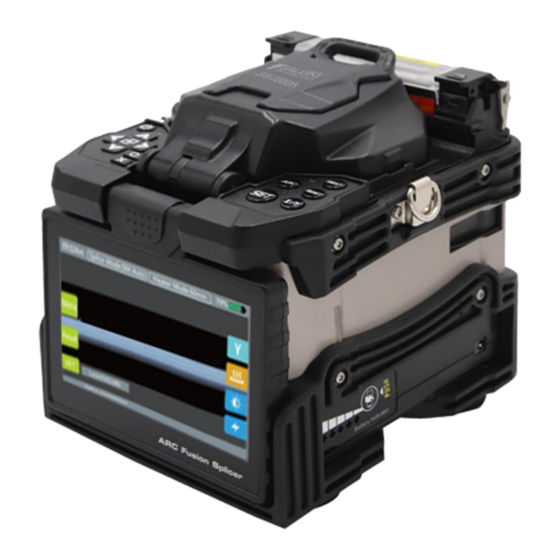
Touch screen application with fully automatic splicing procedures will bring great convenience to users. SFS-7000 series mainly used for the permanent splice of optical fibers, it is widely applied in fiber communication projects and production test of passive optical... - Page 14 Please refer to Fig. 1-1 for the appearance of SFS-7000 Series Optical Fiber Fusion Splicer. Fig. 1-1 Appearance of SFS-7000 Series Optical Fiber Fusion Splicer...
-
Page 15: Chapter 2 Technical Parameters
Chapter 2 Technical Parameters Model SFS-7000H Applicable Fibers SMF (ITU-T G.652), MMF (ITU-T G.651), DSF (ITU-T G.653), NZDSF (ITU-T G.655), BIF (ITU-TG.657) Typical Splice Loss 0.02dB (SMF), 0.01dB (MMF), 0.04dB (DSF), 0.04dB (NZDSF), 0.02dB (BIF) Return Loss ≥ 60dB Compatible Fiber 0.25mm –... - Page 16 Estimated Splice Loss Protection Sleeve 20mm – 60mm Length Results Storage 20000 records & 200 images Tension Test 1.96N – 2.25N Electrode Life 5000 ARCS Display 5 inch color high resolution touch screen, 90° bi-directional view Lighting 3 high-power white LEDs Fiber View &...
- Page 17 Terminal USB, Mini USB 2.0 Power Supply AC input 100-240V, DC input 12-15V Battery Capacity 5200mAh Weight 2.233kg (including battery), 1.853kg (excluding battery) Dimension 140mm*170mm*176mm (including rubber bumper), 130mm*170mm*170mm (excluding rubber bumper) Operating Condition Altitude: 0-5000m above sea level; Temperature:-10 to 50°C; Humidity: 0 to 95%RH, non-dew;...
-
Page 18: Chapter 3 Configuration
Chapter 3 Configuration Standard configuration of SFS-7000 Series Optical Fiber Fusion Splicer is listed in Table 3-1. Table 3-1 Standard package Name Qty. Remarks SFS-7000H host 1 PC Host Fiber cleaver 1 PC Accessory Battery 1 PC Accessory Spare electrode... - Page 19 Alcohol bottle 1 PC Accessory Cleaning brush 1 PC Accessory Fiber stripper 1 PC Accessory Cable stripper 1 PC Accessory Fiber cleaver tray 1 PC Accessory Carrying case 1 PC Accessory...
-
Page 20: Chapter 4 Basic Operation
Chapter 4 Basic Operation 4.1 Appearance overview... - Page 21 4.1.1 Wind-proof cover The wind-proof cover should be kept closed ordinarily and be opened up only when a fiber is placed in the splicer. Close the protector before your operation of the splicer. It comprises...
-
Page 22: Battery Charging
a reflecting mirror for lighting of the microscope and a small head which can stabilize bare fibers in the V-groove. The protector can also prevent wind and dust. 4.1.2 Monitor 5 inch TFT-LCD monitor with 180° adjustable angle and brightness, and can rotate automatically. -
Page 23: Power On
4.3 Power on Press the button on and wait for it to enter into working platform. -
Page 24: Adjust The Brightness Of Lcd Backlight
4.4 Adjust the brightness of LCD backlight In the initial interface, press the to adjust the LCD backlight brightness until clear. -
Page 25: Fiber Preparation Steps
4.5 Fiber preparation steps There are three steps preparing for fibers before splicing. Step 1: Coating stripping Peel off the jacket leaving at least 50mm coating. Remove the coating with a stripper, stripping length should be 30-40mm. Step 2: Use cloth or cotton paper soaked by alcohol density over 99% or high... -
Page 26: Automatic Inspection Of Optical Fiber
density to clean the fiber. Step 3: Cleave the fiber. Use high precise fiber cleaver to cleave the fiber. Please refer to below cleaving example. Tips: Remember to fit the heat shrinkable sleeve before fiber preparation. Make sure the bare optical fiber and its cleaving surface are not stained. ... -
Page 27: Splicing Procedures
Buzzer will alarm if the angle is bigger than the limited value or glitch on the cleaving surface, and there will be warning on the monitor. 4.7 Splicing procedures 1) Turn on the power, when splice SM fiber (ITU-T.G.652), SM mode is suggested. - Page 28 2) Confirm splicing and heating mode, when splice different types of fibers, Auto Mode is suggested, splicing speed will be slower. 3) Clean the fiber or heating shrinkable tube.Penetrate the fiber into heat shrinkable tube. 4) Strip the fiber and clean it with 99% or better purity alcohol. Make sure the coating trash or dirt is wiped out.
- Page 29 5) Please protect the cleaved fiber end from direct touch with any hard object. 6) Place the fiber between the V-groove and two electrodes.
- Page 30 7) Close the wind-proof cover, automatic splicing starts, visual inspection on screen while splicing. Attention: please don’t slide the fiber along the V-groove. The cleaving section should surpass the V-groove but not exceed the mid of both electrodes. 8) Remove the spliced fiber, into the heater tanker; make sure the splicing position in the center of the heat shrinkable sleeve.
-
Page 31: Magnification Function Of The Screen
9) Completed. Attention: when the splicing loss or the altitude change is big. Electrode stabilize and ARC calibration must be executed. 4.8 Magnification function of the screen Users can double click the screen to magnify the monitor so as to inspect the splicing crack and estimate the splicing state. -
Page 33: Chapter 5 Splicing Mode
Chapter 5 Splicing Mode The menu is concise and easy to operate, each splicing mode defines the current splicing mode, time and other important parameter. It’s vital to select the right splicing mode. There is a pre-defined value of the usual fiber type. In this way, it becomes easier to modify the splicing mode and optimize the combination parameter of un-defined fiber type. -
Page 34: Selection Of The Splicing Mode
5.2 Selection of the splicing mode Click enter [Splice Menu]. Enter into the splicing mode and select and press the needed one (yellow font is the current splicing mode). Check the chosen splicing mode and press “Return” to return to the initial interface. -
Page 35: Parameter In General Splicing
5.3 Parameter in general splicing Parameter Description A list of splicing patterns stored in fusion splicer can be copied to Mould the user editable area according to user selected splicing mode. Name Heating of splicing mode not more than 7 characters. Annotation Detailed explanation for splice mode less than 15 characters. - Page 36 Display in [select splice mode] menu. If [pull test] is set [on], after splicing, open the winder-proof Pull test cover, or press [set] button to do pull test. The estimated loss is an estimate of splicing loss. The fusion splicer calculates the loss of the splicing point according to the optical fiber image, and has some deviation from the real value.
- Page 37 Set the overlap amount of fiber pushing, if the [pre-discharging Overlap strength] is low, then smaller [overlap] is recommended and vice versa. The clean discharge can burn the tiny dust on the surface of the Clean discharge time fiber in a small discharge cycle, and the discharge time can be changed by this parameter.
- Page 38 Strength of ARC Set the ARC strength. Splicing ARC time Set the ARC time.
-
Page 39: Chapter 6 Splicing Options
Chapter 6 Splicing Options Enter into [Splice Option] menu, click and choose item, modify parameter. Name Parameter Description Automatic start If Automatic start is set “on”, splicing starts when the Splicing winder-proof cap is closed. Fiber should be prepared options in advance and put into the fusion splicer. - Page 40 Pause one If [pause one] is set “on”, splicing will be ended when the fiber is pushed in right place, and user can see the cleaving angle. Pause two If [pause two] is set “on”, splicing will be ended after completion of alignment.
- Page 41 Fiber space set Pause one Alignment Fiber image Set the fiber display while splicing. Pause two Discharge Estimate...
-
Page 42: Chapter 7 Heating Mode
Chapter 7 Heating Mode There are 50 heating modes stored, 5 default heating modes, user can define and add as they like. Choose the best heating mode and match the used heat shrinkable tube. For each heat sleeve, user can edit and define the corresponding parameters. 7.1 Selection for heating mode Choose and enter into [Heater Menu]. - Page 43 Choose the needed mode, then press until the font become yellow. This is the current heating mode. Check the chosen heating mode, press back to return to the initial interface.
-
Page 44: Edit The Heating Mode
7.2 Edit the heating mode Heating conditions stored in “heating mode” can be edited and modified. Enter into [Heater Menu] and edit, select [Edit] to enter into [Edit Heater Mode]. - Page 45 Choose and edit the parameter, after which, press [Confirm].
-
Page 46: Delete Heating Mode
7.3 Delete heating mode Enter into [Heater Menu], choose the mode you want to delete, press [Delete], press [Confirm] on the tooltip. - Page 47 Parameter Description Name Name of heating mode. Select [full] (heating all) or [part] (heating part of it) according to Heating type users requirements. Heating temperature Set heating temperature. Heating time Set the heating time from start to end.
-
Page 48: Chapter 8 System Maintenance
Chapter 8 System Maintenance 8.1 Dust checking The fusion splicer detects the dust on fiber, camera or objective by imaging, which can influence the splicing result. This function can detect the dust on the optical channel and judge whether it will influence splicing quality or not. Operations ... -
Page 49: Arc Calibration
8.2 ARC calibration Motors are adjusted before exit-factory. Certainly, these settings may change for a variety of reasons. This function automatically calibrates the speed of 4 motors. Operations Choose [ARC calibration] in [system maintenance]. Prepare for the fiber and put into fusion splicer, press [set] to start . ... -
Page 50: Electrode Stabilize
the fiber will be shifted relative to the discharge center, ARC calibration will be needed. 8.3 Electrode stabilize When the environment changes dramatically, the discharge strength will become unstable which will increase the splicing loss, especially when it changes from low altitude to high altitude, it needs some time to stabilize the discharge strength. -
Page 51: Electrode Setting
b. Splicing the fiber quickly. The electrode position is accurately measured 16 times of electrode stabilize. 8.4 Electrode setting The splicing loss will be enlarged and splicing strength will be reduced when the discharging times exceed the electrode life. The electrode is worn by use and must be regularly cleared according to the concentration of the oxide. - Page 52 Be careful not to pull the wiring out when replacing the electrode bars. Clean the new electrode bar with a clean swab or dust-free cloth soaked in alcohol, then install to the fusion splicer, place the electrode cover and tighten screws.
-
Page 53: Chapter 9 Other Functions And Applications
Chapter 9 Other Functions and Applications 9.1 Records storage Max. 20000 splice results can be stored. The storage contents is varied from splice modes to splice modes. Display of splicing records The storage results can be displayed in fusion splicer. ... -
Page 54: System Settings
ON in Stored Records. 9.2 System settings Parameter Description Buzzer Set the turn on/off switch. Temperature unit Set the display way of temperature. If select [ON], when fiber is put into heat tanker, it will automatic Automatic heating start to heat. Language Select the operating language. - Page 55 recommended to set it as [2000] times. When the discharging times exceed the set data, there will be Electrode use warning warning after turning-on [must change the electrode bar]. and it is recommended to set the parameter as [3000] times. If without any operations, monitor will be turned off automatically within 180 seconds (user can change the time) to avoid loss of Turn off the monitor...
-
Page 56: Chapter 10 Operation Faults And Solutions
Chapter 10 Operation Faults and Solutions 10.1 Excessive Splicing Loss and Solutions Image Definition Reason Solution Fiber core axial There is dust on the Clean V-groove and deviation V-groove or fiber clamp. fiber clamp. 1) There is dust on 1) Clean V-groove and Fiber core angle V-groove or fiber clamp. - Page 57 1) Poor quality of fiber 1) Check the fiber end face. cleaver working state. Dust combustion 2) Dust is not cleaned or 2) Clear the fiber or cleared when cleaning increase the [cleaning the fiber or discharging. discharging time]. 1) Poor quality of fiber 1) Check the fiber end face.
-
Page 58: Common Error And Solutions
1) Discharging strength Adjust [splicing not suitable. discharging strength] Too thin 2) Some discharge [discharging time] or parameters are not increase [overlap suitable. amount]. Adjust [splicing Some discharge discharging strength] Splicing line parameters are not [discharging time] or suitable. increase [overlap amount]. - Page 59 Error message Reason Solution The fiber end-face is placed Press RESET, and set the fiber and Left/right fiber on the electrode centerline end-face between the electrode centerline place error or beyond it. and the V-groove edge. The fiber is not correctly Pushing motor placed at the bottom of the Press RESET, and put the fiber correctly.
-
Page 60: Common Faults And Solutions
2) [Clean angle limit] is set If the blade is worn, rotate the blade. too low. 2) Set the [Clean angle limit] to a proper value. (standard 3.0°) 1) [Clean angle limit] is set 1) Set the [Clean angle limit] to a proper Core angle too low. - Page 61 1) When the memory effect occurs when the battery is reduced or after a long period of storage, the battery Full battery but can only do several should be completely let go, and then recharge the splices battery. 2) Battery worn, change the battery. 3) Use the machine under too low temperature.
- Page 62 The splicer turned off automatically when the machine The splicer suddenly shut down is set for automatic machine shutdown (default 30 minutes) without any operations. AUTO mode only for standard SM, MM, NZ optical Fiber identification errors under fibers. When splice special fibers, AUTO mode may AUTO mode not recognize correctly.
- Page 63 After discharge calibration, the The discharge calibration changes the internal discharge intensity did not change condition parameters, not the discharging strength. Pressing RESET button is useless under this Forget to put fiber when fiber is circumstance. Please open the shield cover, put the needed to be put in the maintenance cleaved fiber into V-groove and press [Set] to execute.
Need help?
Do you have a question about the SFS-7000 Series and is the answer not in the manual?
Questions and answers