Table of Contents
Advertisement
Quick Links
A MIDDLEBY COMPANY
OWNER'S
OPERATING
& INSTALLATION
MANUAL
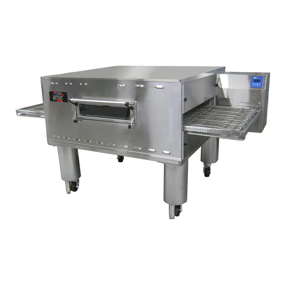
PS360E-Series Electric Ovens
Model PS360E
Model PS360EW
© 2021 Middleby Marshall Inc.
is a registered trademark of Middleby Marshall, Inc. All rights reserved.
1
PS360E-Series Electric Ovens: English
Combinations:
• Single Oven
• Double Oven (Two-Stack)
• Triple Oven (Three-Stack)
P/N
78005 rev A
Advertisement
Table of Contents


Need help?
Do you have a question about the PS360E Series and is the answer not in the manual?
Questions and answers