Advertisement
Quick Links
A310-FM -- Installation Guide
Permanent Table Installation
The tube and wing nut required to install the rack tray are included with the MXA310 microphone. Refer to the
MXA310 user guide for replacement part information.
Tip: This process assumes that both ends of the network cable are accessible. If the other end of the network ca
ble is not accessible, before installing the tube and plugging in the microphone (step 2), you must guide the cable
through the hardware components in the following order:
1. Wing nut (see image for correct orientation)
2. Bracket (under table)
3. Table
4. Tray (above table)
1/9
Advertisement

Related Manuals for Shure A310-FM


Summary of Contents for Shure A310-FM
- Page 1 A310-FM -- Installation Guide Permanent Table Installation The tube and wing nut required to install the rack tray are included with the MXA310 microphone. Refer to the MXA310 user guide for replacement part information. Tip: This process assumes that both ends of the network cable are accessible. If the other end of the network ca...
-
Page 2: Installation Process
Shure Incorporated Installation Process 1. Remove the 3 screws located in the center on the bottom of the microphone... - Page 3 Shure Incorporated 2. Plug a network cable into the microphone and guide it through the center exit path. When the cable is secured, guide it through the tube. Note: If necessary, remove the retaining tabs to install thicker cable. Replace them after the cable is installed.
- Page 4 Shure Incorporated 3. Align the tube into the recessed area in the center of the microphone. Install the 3 screws (removed in step 1) to secure the tube.
- Page 5 Shure Incorporated 4. Drill a 143 mm (5 5/8 in.) hole through the table, and then place the tray into the hole.
- Page 6 5. Guide the cable through the hole in the center of the tray. Then, place the tube through the hole in the table and gently press the microphone into the tray. Align the Shure logo on the microphone with the Shure logo on...
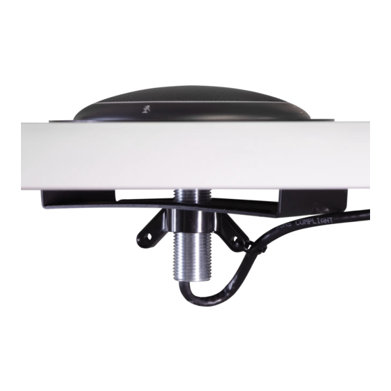
- Page 7 Shure Incorporated 6. Place the bracket underneath the table, with the tube going through the hole. For thicker tables (≥ 55 mm), turn the bracket upside down for additional clearance. Note: maximum table thickness = 73 mm (2.87 in).
- Page 8 Shure Incorporated 7. Guide the cable through the wing nut, and attach the wing nut onto the tube from underneath the table. Then, tighten the wing nut to secure the bracket against the table. Optional: use the hole in the wing nut to insert a cable tie for cable management.
- Page 9 Shure Incorporated Dimensions...
Need help?
Do you have a question about the A310-FM and is the answer not in the manual?
Questions and answers