Ingersoll-Rand 41-EU Series Maintenance Information
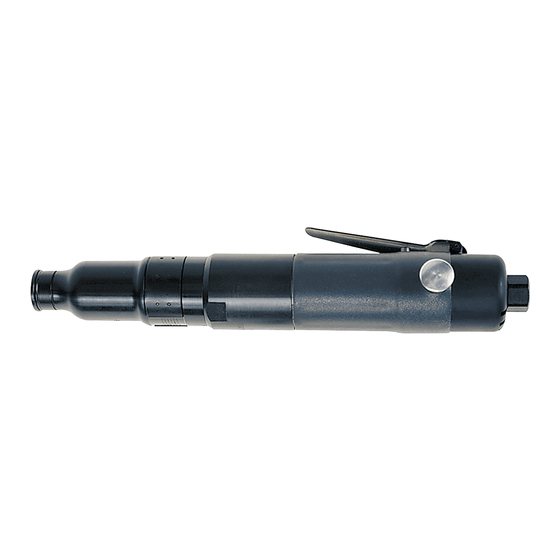
Air screwdriver
Hide thumbs
Also See for 41-EU Series:
- Product information (52 pages) ,
- Product information (56 pages) ,
- Instructions manual (62 pages)

Related Manuals for Ingersoll-Rand 41-EU Series


Summary of Contents for Ingersoll-Rand 41-EU Series
- Page 1 47135470 Edition 1 January 2010 Air Screwdriver 41-EU Series Maintenance Information Save These Instructions...
- Page 2 WARNING Always wear eye protection when operating or performing maintenance on this tool. Always turn off the air supply and disconnect the air supply hose before installing, removing or adjusting any accessory on this tool or before performing any maintenance on this tool. Note: When reading the instructions, refer to exploded diagrams in parts Information Manuals when applicable (see under Related Documentation for form numbers).
- Page 3 4. Remove two Balls (9), Valve Body (10) and Spring (11). 6. For Lever Throttle models, remove Throttle Pin (17) and 5. Remove Screen (8) from Inlet Adapter. Spring (16). Assembly 6. Install Exhaust cap to Housing, being certain Balls (9) remain NOTICE properly positioned in Housing and Reverse Valve.
- Page 4 10. Install Snap Ring (71). 5. Use the recommended lubricant to lubricate ball pockets of Bit 11. Coat Pin (88) with the recommended lubricant then slide Spring Holder and install six Balls (106) into pockets, securing with Thrust (87) over Pin. Install Pin (88) and Spring (87) into Spindle. Race (101).
- Page 5 Notes:...
- Page 6 Notes:...
- Page 7 Notes:...
- Page 8 www.ingersollrandproducts.com © 2010 Ingersoll Rand Company...
Need help?
Do you have a question about the 41-EU Series and is the answer not in the manual?
Questions and answers