National Instruments Compact FieldPoint cFP-21 Series User Manual
Hide thumbs
Also See for Compact FieldPoint cFP-21 Series:
- Quick start manual (28 pages) ,
- Quick start manual (28 pages) ,
- Quick start manual (30 pages)

Subscribe to Our Youtube Channel
Related Manuals for National Instruments Compact FieldPoint cFP-21 Series


Summary of Contents for National Instruments Compact FieldPoint cFP-21 Series
- Page 1 Compact FieldPoint cFP-21xx and cFP-BP-x User Manual cFP-21xx and cFP-BP-x User Manual February 2005 371380B-01...
- Page 2 For further support information, refer to the Technical Support and Professional Services appendix. To comment on National Instruments documentation, refer to the National Instruments Web site at ni.com/info and enter the info code feedback. © 2005 National Instruments Corporation. All rights reserved.
- Page 3 The reader should consult National Instruments if errors are suspected. In no event shall National Instruments be liable for any damages arising out of or related to this document or the information contained in it.
- Page 4 Conventions The following conventions appear in this manual: » The » symbol leads you through nested menu items and dialog box options to a final action. The sequence File»Page Setup»Options directs you to pull down the File menu, select the Page Setup item, and select Options from the last dialog box.
-
Page 5: Table Of Contents
Guarding against Other System Failures (Hardware Watchdog) ........3-1 Storing a Custom Power-Up Configuration..............3-2 Setting a Power-Up State with the Snapshot Feature........3-2 Configurable Power-Up States ................3-2 Inserting, Removing, and Replacing I/O Modules ............3-2 © National Instruments Corporation cFP-21xx and cFP-BP-x User Manual... - Page 6 Contents LED Indicators ......................3-3 POWER LED ....................3-3 STATUS LED....................3-3 LINK ACT LED ..................... 3-3 100 Mbps LED....................3-4 User-Configurable LEDs A–D................ 3-4 Power-On Self Test (POST) ................3-4 DIP Switches ......................... 3-5 CONSOLE OUT Switch ................. 3-6 DISABLE VI Switch ..................
- Page 7 FieldPoint OPC Server and the cFP-21xx ............5-2 Data Communications ..................5-3 DataSocket ..................5-4 Publish Data VI .................5-5 Serial VIs...................5-6 TCP and UDP VIs................5-6 Appendix A Troubleshooting Appendix B Specifications Appendix C Technical Support and Professional Services Glossary Index © National Instruments Corporation cFP-21xx and cFP-BP-x User Manual...
-
Page 8: Overview Of Compact Fieldpoint
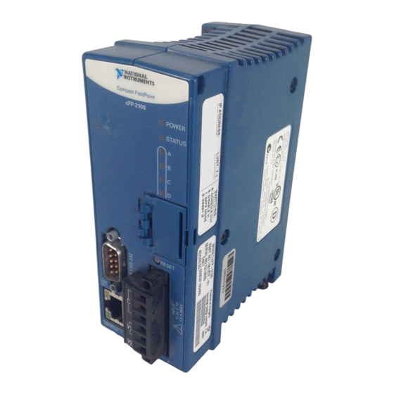
Figure 1-1 shows where all of these features are located on the cFP-21xx. The figure indicates which features are available only on specific models such as the cFP-2120. © National Instruments Corporation cFP-21xx and cFP-BP-x User Manual... - Page 9 Chapter 1 Overview of Compact FieldPoint Compact FieldPoint cFP-21 xx POWER STATUS COM 4 / RS-485 COM 3 / RS-232 RESET INPUT 11-30 V-- LINK 1.5 A MAX COM 2 / RS-232 DI / DO 100 Mbps Front Bottom 1 Ethernet Port 7 Power Connector 2 RS-232 Serial Port 8 Switch Input/LED Output Terminals (cFP-2120 Only)
-
Page 10: Fieldpoint Software Overview
• VI Logger support You can download a current version of FieldPoint software from the National Instruments Web site. Using your Web browser, go to ni.com select Support»Drivers and Updates»Current Software Versions» Distributed I/O—FieldPoint, then select the latest version of NI-FieldPoint. - Page 11 Chapter 1 Overview of Compact FieldPoint Install software as described in Chapter 2, Installing Compact FieldPoint Hardware and Software. Install programming software (LabVIEW Real-Time). Install FieldPoint software. Configure Compact FieldPoint system and verify configuration as described in the Measurement & Automation Explorer Help for FieldPoint.
-
Page 12: Installing Compact Fieldpoint Hardware And Software
1/8 in. flathead and number 2 Phillips screwdrivers ❑ NI-FieldPoint software version 4.1.1 ❑ A host PC running Windows 2000/NT 4.0 ❑ LabVIEW Real-Time software Using FieldPoint software with Windows NT 4.0 requires Service Pack 6 or later. © National Instruments Corporation cFP-21xx and cFP-BP-x User Manual... -
Page 13: Compact Fieldpoint Safety Information
You can compromise the safety protection built into the product if the product is damaged in any way. If the product is damaged, return it to National Instruments for repair. Do not substitute parts or modify the Compact FieldPoint product. Use the product only with the modules, accessories, and cables specified in the installation instructions. - Page 14 Working voltage is the highest rms value of an AC or DC voltage that can occur across any particular insulation. MAINS is defined as a hazardous live electrical supply system that powers equipment. Suitably rated measuring circuits may be connected to the MAINS for measuring purposes. © National Instruments Corporation cFP-21xx and cFP-BP-x User Manual...
-
Page 15: Mounting The Compact Fieldpoint Backplane
Chapter 2 Installing Compact FieldPoint Hardware and Software installations, distribution boards, and circuit breakers. Other examples are wiring, including cables, bus-bars, junction boxes, switches, socket-outlets in the fixed installation, and stationary motors with permanent connections to fixed installations. • Installation Category IV is for measurements performed at the primary electrical supply installation (<1,000 V). - Page 16 (17.4 in.) 127 mm (5.00 in.) Min 165 mm (6.50 in.) Cabling Cooling Outline Clearance 51–76 mm (2–3 in.) All Around Figure 2-3. cFP-BP-x Backplane with cFP-21xx Installed, Front View with Dimensions © National Instruments Corporation cFP-21xx and cFP-BP-x User Manual...
-
Page 17: Mounting The Backplane On A Panel
Chapter 2 Installing Compact FieldPoint Hardware and Software NI recommends that you use one of the mounting systems described in this Caution document. If you decide to use a custom mounting solution, make sure that the screws you use are short enough to fit in the holes in the backplane. The screw holes are 5 mm (0.2 in) deep. - Page 18 3/4 in. from each side of the backplane. NI also offers a vertical panel-mount kit that extends from the top and bottom of the backplane and is flush with the sides. The vertical panel-mount kit is part number 778688-01. © National Instruments Corporation cFP-21xx and cFP-BP-x User Manual...
-
Page 19: Mounting The Backplane In A Standard 19-In. Rack
Chapter 2 Installing Compact FieldPoint Hardware and Software Mounting the Backplane in a Standard 19-in. Rack In order to mount the cFP-BP-x backplane in an EIA standard 19-in. rack, you need the rack-mount kit. You can order the kit, part number 778615-01, from NI. - Page 20 Installing Compact FieldPoint Hardware and Software T IO IN S Figure 2-8. Fastening the Rack-Mount Accessory to the cFP-BP-4 Backplane T IO IN S Figure 2-9. Fastening the Rack-Mount Accessory to the cFP-BP-8 Backplane © National Instruments Corporation cFP-21xx and cFP-BP-x User Manual...
-
Page 21: Installing A Din Rail In The Rack-Mount Accessory
Chapter 2 Installing Compact FieldPoint Hardware and Software Bolt the rack-mount accessory to a standard 19 in. rack. Connect the safety ground as explained in the Compact FieldPoint Safety Information section. Disconnect power before removing the backplane from the rack. Caution Installing a DIN Rail in the Rack-Mount Accessory If you are using a rack-mounted cFP-BP-4, you can install a short... -
Page 22: Mounting The Cfp-Bp-4 On A Din Rail
Figure 2-11. Fastening the DIN Rail Clip to the cFP-BP-4 Backplane Insert one edge of the DIN rail into the deeper opening of the DIN rail clip, as shown in Figure 2-12. © National Instruments Corporation 2-11 cFP-21xx and cFP-BP-x User Manual... -
Page 23: Installing The Cfp-21Xx Controller On A Compact Fieldpoint Backplane
Chapter 2 Installing Compact FieldPoint Hardware and Software 1 DIN Rail Clip 2 DIN Rail Clip Spring 3 DIN Rail Figure 2-12. One Edge of DIN Rail Inserted in Clip Press down firmly on the backplane to compress the spring until the clip locks in place on the DIN rail. -
Page 24: Installing I/O Modules On The Backplane
Using a number 2 Phillips screwdriver with a shank of at least 64 mm (2.5 in.) length, tighten the captive screws to 1.1 N ⋅ m (10 lb ⋅ in.) of torque. The nylon coating on the screws prevents them from loosening. © National Instruments Corporation 2-13 cFP-21xx and cFP-BP-x User Manual... -
Page 25: Connecting To Field Devices
Chapter 2 Installing Compact FieldPoint Hardware and Software 1 cFP I/O Module 3 Screw Holes 2 Captive Screws 4 cFP-BP-4 Backplane Figure 2-14. Installing an I/O Module on the Backplane (cFP-BP-4 Shown) Repeat this procedure to install additional I/O modules on the backplane. -
Page 26: Installing Connector Blocks On The Backplane
1 cFP-CB-x Connector Block 3 Screw Holes 2 cFP I/O Module 4 Connector Slot Figure 2-15. Installing a cFP-CB-x Connector Block Repeat this procedure to install additional connector blocks on the backplane. © National Instruments Corporation 2-15 cFP-21xx and cFP-BP-x User Manual... -
Page 27: Connecting The Cfp-21Xx To A Network
Chapter 2 Installing Compact FieldPoint Hardware and Software Connecting the cFP-21xx to a Network Connect the cFP-21xx controller to an Ethernet network using the RJ-45 Ethernet port on the module. Use a standard Category 5 Ethernet cable to connect the cFP-21xx to an Ethernet hub, or use an Ethernet crossover cable to connect the module directly to a computer. -
Page 28: Powering Up The Cfp-21Xx
You should see the POWER and STATUS LEDs come on. After about five seconds, the STATUS LED begins flashing. The cFP-21xx is ready to be configured, and you can install the FieldPoint software. © National Instruments Corporation 2-17 cFP-21xx and cFP-BP-x User Manual... -
Page 29: Installing Software On The Host Pc
Chapter 2 Installing Compact FieldPoint Hardware and Software If you have already assigned an IP address to the cFP-21xx, the STATUS LED turns off, the I/O module READY LEDs come on, and the cFP-21xx is ready for use. The total boot time for a configured system is 15–20 seconds. -
Page 30: Feature Descriptions
(the watchdog state). The network watchdog is disabled by default. Note National Instruments recommends leaving the network watchdog disabled when you are running embedded applications on the cFP-21xx. Refer to the section of this chapter for information about the hardware watchdog for embedded applications. -
Page 31: Storing A Custom Power-Up Configuration
Chapter 3 Feature Descriptions Storing a Custom Power-Up Configuration Setting a Power-Up State with the Snapshot Feature The Snapshot feature stores the current state of the Compact FieldPoint hardware for use as the power-up state of the system. Caution Using the Snapshot feature overwrites any power-up values you have specified for individual channels. -
Page 32: Led Indicators
The yellow LINK ACT LED blinks when the cFP-21xx receives data from or transmits data to the Ethernet. Unrelated network activity causes this LED to blink occasionally even when the cFP-21xx is inactive. © National Instruments Corporation cFP-21xx and cFP-BP-x User Manual... -
Page 33: User-Configurable Leds A-D
Chapter 3 Feature Descriptions 100 Mbps LED The green 100 Mbps LED is lit when the cFP-21xx is communicating at 100 megabits per second. If the 100 Mbps LED is not lit, the cFP-21xx is communicating at 10 megabits per second. User-Configurable LEDs A–D LEDs B, C, and D can be sent values of 0, 1, or 2. -
Page 34: Dip Switches
SAFE MODE, and RESET IP switches. The cFP-21xx reads these switches only when powering up or rebooting. You must reboot the module with one of these switches ON for its setting to take effect. © National Instruments Corporation cFP-21xx and cFP-BP-x User Manual... -
Page 35: Console Out Switch
Chapter 3 Feature Descriptions CONSOLE OUT Switch With a serial-port terminal program, you can use the Console Out switch to read the IP address and BIOS version of the controller. Connect the serial port on the controller to a computer. Push the switch to the ON position. Make sure that the serial-port terminal program is configured to the following settings: •... -
Page 36: Reset Ip Switch
DB-9 connector pins and Table 3-2 lists the signals on the pins. PIN 5 PIN 9 PIN 6 PIN 1 Figure 3-2. DB-9 Connector Pin Locations Table 3-2. DB-9 Pin Descriptions DB-9 Pin RS-232 Signal © National Instruments Corporation cFP-21xx and cFP-BP-x User Manual... -
Page 37: Com 2 (Cfp-2110 And Cfp-2120 Only)
Chapter 3 Feature Descriptions Table 3-2. DB-9 Pin Descriptions (Continued) DB-9 Pin RS-232 Signal COM 2 (cFP-2110 and cFP-2120 Only) COM 2 is an RS-232 DTE serial port with a 10-position modular jack. The Serial Port VIs access COM 2 as port 1. Refer to Figure 3-3 and Table 3-3 for pin locations and signal descriptions. - Page 38 COM 4 FP-1001 FP-1001 RXD– RXD+ TXD– TXD+ RX– TX– RX– TX– 120 Ω 120 Ω 120 Ω 120 Ω Figure 3-4. Wiring for an RS-485 Network Controlled by the cFP-2120 © National Instruments Corporation cFP-21xx and cFP-BP-x User Manual...
-
Page 39: External Switch Inputs And Led Outputs (Cfp 2120 Only)
Chapter 3 Feature Descriptions COM 4 is designed to operate in four-wire mode as shown in Figure 3-4. You can use COM 4 in two-wire mode, but you must design your application so that it filters out the writes that echo back over the read channels. -
Page 40: Power Source (Isolated Power Connector)
In order to get data from the compact flash while the controller is operating, use an FTP client or a LabVIEW remote front panel and download the data from the D drive on the controller. © National Instruments Corporation 3-11 cFP-21xx and cFP-BP-x User Manual... -
Page 41: File Transfer Capability
Chapter 3 Feature Descriptions File Transfer Capability When running on a cFP-21xx, the Real-Time Engine has a File Transfer Protocol (FTP) server. The FTP server gives you the ability to use any standard FTP utility for transferring files to and from the hard drive of the cFP-21xx. -
Page 42: Labview Real-Time Programming
LabVIEW Real-Time when targeted to the cFP-21xx: • ActiveX • Front panel datalogging • Dialog boxes • Printing • Programmatic menus • Front panel Web publishing • NI driver software for non-FieldPoint hardware © National Instruments Corporation cFP-21xx and cFP-BP-x User Manual... - Page 43 Chapter 4 LabVIEW Real-Time Programming LabVIEW Real-Time applications that have any of the unsupported functionality previously listed may or may not work as expected on the cFP-21xx. Complete the following steps on the host PC to target LabVIEW Real-Time to the cFP-21xx: Start LabVIEW.
-
Page 44: Targeting Labview Real-Time To The Host Pc
VI Server and Web Server options. You also can use the following two additional groups of options for LabVIEW Real-Time applications on networked cFP-21xx modules: RT Target: Access and RT Target: Miscellaneous. © National Instruments Corporation cFP-21xx and cFP-BP-x User Manual... -
Page 45: Rt Target: Access
Chapter 4 LabVIEW Real-Time Programming RT Target: Access Use RT Target: Access options to limit which host PCs can target the Real-Time Engine on the cFP-21xx. Complete the following steps to open the RT Target: Access dialog box: Target LabVIEW Real-Time to the cFP-21xx. Refer to the Targeting LabVIEW Real-Time to the cFP-21xx section for more information. - Page 46 Additionally, the hosts test.site.com , and also a.test.site.com b.test.site.com 130.164.123.123 can target the Real-Time Engine. The host does not public.site.com have access, even though it is in the domain. site.com © National Instruments Corporation cFP-21xx and cFP-BP-x User Manual...
-
Page 47: Rt Target: Miscellaneous
Chapter 4 LabVIEW Real-Time Programming The default RT Target: Access settings permit any host machine to target the Real-Time Engine on the cFP-21xx without a password. Note If the cFP-21xx does not have access to a Domain Name Server (DNS), do not use domain name entries in the RT Target Access List. -
Page 48: Embedding Applications On The Cfp-21Xx
Application Builder can be embedded on the cFP-21xx. This section explains how to embed LabVIEW Real-Time applications on the cFP-21xx by using the Application Builder while LabVIEW Real-Time is targeted to the controller. © National Instruments Corporation cFP-21xx and cFP-BP-x User Manual... -
Page 49: Command Line Arguments
Chapter 4 LabVIEW Real-Time Programming Refer to the LabVIEW Help for more information about building LabVIEW Real-Time applications on the host PC. Refer to the LabVIEW Application Builder Release Notes and to the LabVIEW Help for more information about using the Application Builder on the host PC. Command Line Arguments Use command line arguments for applications built on the host PC to disable the Select Target Platform dialog box and to explicitly specify a... -
Page 50: Target Tab
Application name, Destination directory, and Support file directory settings in the Application Builder when you target LabVIEW Real-Time to the cFP-21xx. Refer to the RT Target Options section for more information about accessing and using RT Target Options. © National Instruments Corporation cFP-21xx and cFP-BP-x User Manual... -
Page 51: Source Files And Vi Settings Tabs
Chapter 4 LabVIEW Real-Time Programming If you select Small target with external file for subVIs in the Build Options pane, you cannot change the LLB for other files path because this path is determined from the Application Path setting in Network Options. -
Page 52: Accessing Cfp-21Xx Channels From Pc Applications
In addition, a set of sample projects is placed in your LabWindows/ directory. Using these examples is the best way to get CVI Samples familiar with these functions. The FieldPoint LabWindows/CVI Interface © National Instruments Corporation cFP-21xx and cFP-BP-x User Manual... -
Page 53: Fieldpoint Opc Server And The Cfp-21Xx
Launch your OPC client. Open the FieldPoint OPC server, , from the OPC client. National Instruments.OPCFieldPoint This server was registered with Windows when you installed the FieldPoint software. OPC clients should be able to show you a list of available registered servers, but you may have to type this name in yourself. -
Page 54: Data Communications
FieldPoint systems, computers, and devices. The most common methods are to use DataSocket, serial VIs, TCP VIs, UDP VIs, or Data Publishing VIs, as described in the following sections. © National Instruments Corporation cFP-21xx and cFP-BP-x User Manual... -
Page 55: Datasocket
Chapter 5 Accessing cFP-21xx Channels from PC Applications DataSocket DataSocket, a programming technology based on TCP/IP, simplifies live data exchange between different applications on one computer or between computers connected on a network. DataSocket was designed as an easy-to-use, high-performance programming interface for sharing and publishing live data in measurement and automation applications. -
Page 56: Publish Data Vi
Publish Data VI You can use the Publish Data VI on the FieldPoint palette to create items and groups that are published using the National Instruments Ethernet (Logos) protocol. A host computer or cFP-21xx can link to these items using DataSocket or using the native connection capabilities of Lookout or the LabVIEW DSC module. -
Page 57: Serial Vis
Chapter 5 Accessing cFP-21xx Channels from PC Applications Serial VIs You can use the LabVIEW Serial VIs to communicate with other serial devices through the serial port(s) on the cFP-21xx. For more information about the cFP-21xx serial port(s), refer to the Serial Ports section of Chapter 3,... -
Page 58: Appendix A Troubleshooting
Error Condition 0 (stays lit) The cFP-21xx did not power on correctly. Contact National Instruments for assistance. The cFP-21xx is in reset mode or is unconfigured. Make sure the RESET IP switch is in the OFF position and restart the controller. Refer to the Measurement &... - Page 59 ON position. 4 (or more) The cFP-21xx has detected an unrecoverable error. Contact National Instruments for assistance. Other Indications of Trouble with the Controller • Red status LED stays lit when controller is in normal mode •...
- Page 60 After formatting, you must reconfigure network settings and reinstall software. Remember to install LabVIEW Real-Time 6.1.3 or later on the controller, because previous versions do not work with the controller. © National Instruments Corporation cFP-21xx and cFP-BP-x User Manual...
-
Page 61: Appendix B Specifications
128 MB DRAM cFP-2120 ..........128 MB nonvolatile 128 MB DRAM Memory lifetime (nonvolatile)....300,000 writes per sector Serial Ports cFP-2100 ..........One RS-232 serial port cFP-2110 ..........Two RS-232 serial ports © National Instruments Corporation cFP-21xx and cFP-BP-x User Manual... - Page 62 Appendix B Specifications cFP-2120..........Three RS-232 serial ports, one RS-485 serial port RS-232 (DTE) serial ports Baud rate..........110–115,200 bps Data bits...........5, 6, 7, 8 Stop bits ...........1, 1.5, 2 Parity..........Odd, Even, Mark, Space Flow control........RTS/CTS, XON/XOFF, DTR/DSR RS-485 (DTE) ports Baud rate..........110–115,200 bps Data bits...........5, 6, 7, 8 Stop bits ...........1, 1.5, 2 Parity..........Odd, Even, Mark, Space...
- Page 63 (IEC 60068-2-64) ........10–500 Hz, 5 g Operating shock (IEC 60068-2-27) ........50 g, 3 ms half sine, 18 shocks at 6 orientations; 30 g, 11 ms half sine, 18 shocks at 6 orientations © National Instruments Corporation cFP-21xx and cFP-BP-x User Manual...
- Page 64 Appendix B Specifications Safety This product is designed to meet the requirements of the following standards of safety for electrical equipment for measurement, control, and laboratory use: • IEC 61010-1, EN 61010-1 • UL 61010-1 • CAN/CSA-C22.2 No. 61010-1 For UL and other safety certifications, refer to the product label, or visit Note , search by model number or product line, and click the ni.com/certification...
- Page 65 Figure B-1 shows the connector pinouts for FieldPoint Ethernet cables. Connector 1 Connector 2 pin 1 pin 8 pin 1 pin 8 Figure B-1. Ethernet Cable Pinout © National Instruments Corporation cFP-21xx and cFP-BP-x User Manual...
- Page 66 Technical Support and Professional Services Visit the following sections of the National Instruments Web site at for technical support and professional services: ni.com • Support—Online technical support resources at ni.com/support include the following: – Self-Help Resources—For answers and solutions, visit the...
- Page 67 Appendix C Technical Support and Professional Services • Calibration Certificate—If your product supports calibration, you can obtain the calibration certificate for your product at ni.com/calibration If you searched and could not find the answers you need, contact ni.com your local office or NI corporate headquarters. Phone numbers for our worldwide offices are listed at the front of this manual.
- Page 68 DIP switch Dual inline package switch. Domain name server. File Transfer Protocol. HotPnP Hot plug-and-play. Input/output. International Electrotechnical Commission. Light-emitting diode. Meters. OLE for Process Control. Pulse generation. POST Power-on self test. © National Instruments Corporation cFP-21xx and cFP-BP-x User Manual...
- Page 69 Glossary Pulse-width modulation. Generation of a pulse waveform with fixed frequency and variable pulse width (duty cycle). PWM is used to control discrete devices such as DC motors and heaters by varying the pulse width (the ration of on time to off time). subnet A set of systems whose IP addresses are configured such that they can communicate directly with one another.
- Page 70 B-1 cFP-21xx cFP-BP-x, figure, 2-5 overview, 1-1 cleaning cFP-21xx, 2-2 setup overview, 1-3 Compact FieldPoint cFP-21xx controller safety information, 2-2 configurable power-up states, 3-2 system (definition), 1-2 data communication methods, 5-3 © National Instruments Corporation cFP-21xx and cFP-BP-x User Manual...
- Page 71 3-9, 3-10, 3-11 file transfer capability, 3-12 DIN rail mount. See installation, mounting hardware on DIN rail National Instruments FTP site, 1-3 DIO, 3-9, 3-10, 3-11 RT Engine FTP server, 3-12 DIP switches, 3-5 DISABLE VI switch, 3-6...
- Page 72 LED output, 3-9, 3-10, 3-11 IP address, resetting with Reset switch, 3-7 LINK LED, 3-3 isolation, defeated by cascading power local bus connector, 1-2, 2-4, 2-5, 2-13 (caution), 2-17 KnowledgeBase, C-1 © National Instruments Corporation cFP-21xx and cFP-BP-x User Manual...
- Page 73 A-1 mounting, figure, 2-4 power-up states, configurable, 3-2 programming examples (NI resources), C-1 National Instruments support and services, C-1 rack mount. See installation, mounting network specifications, B-1 hardware in rack network watchdog, 3-1...
- Page 74 STATUS LED, 3-3 diagrams, 3-9, 3-11 error indications (table), A-1 Ethernet cables, B-5 switch input, 3-9, 3-10, 3-11 Ethernet connections, 2-16 switches, DIP switches, 3-5 field devices, 2-14 power, 2-16 © National Instruments Corporation cFP-21xx and cFP-BP-x User Manual...
Need help?
Do you have a question about the Compact FieldPoint cFP-21 Series and is the answer not in the manual?
Questions and answers