Table of Contents
Advertisement
Quick Links
Quick Start Guide
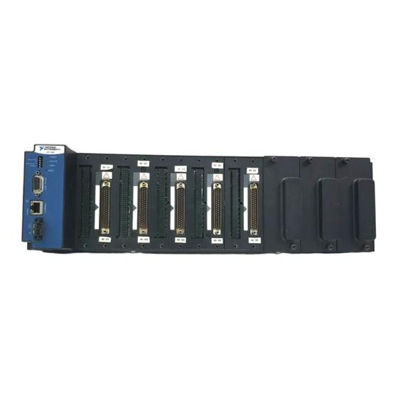
FieldPoint cFP-21xx
What You Need to Get Set Up
•
cFP-21xx LabVIEW RT controller
•
Mounting hardware (DIN rail,
panel-mount, or rack-mount
accessory)
•
I/O module(s)
•
cFP-BP-x backplane, connector
blocks, cables
™
•
11–30 VDC power supply
•
Accessories: Ethernet cable,
number 2 Phillips screwdriver
•
PC running Windows
•
FieldPoint software 4.1.1 or later
•
LabVIEW Real-Time Module
Advertisement
Table of Contents

Related Manuals for National Instruments FieldPoint cFP-1808


Summary of Contents for National Instruments FieldPoint cFP-1808
- Page 1 Quick Start Guide FieldPoint cFP-21xx ™ What You Need to Get Set Up • cFP-21xx LabVIEW RT controller • 11–30 VDC power supply • Mounting hardware (DIN rail, • Accessories: Ethernet cable, panel-mount, or rack-mount number 2 Phillips screwdriver accessory) •...
- Page 2 1. Mount the Compact FieldPoint Backplane You can mount the cFP-BP-x backplane on a 35mm DIN rail, on a panel, or in a standard 19 in. rack. Before using any of these mounting methods, record the serial number from the back of the backplane. Each set of mounting instructions in this document includes an instruction to connect the protective earth (PE) ground terminal on the cFP-BP-x backplane to the system safety ground.
- Page 3 Cooling Outline 51 mm (2 in.) If you are using UL Recognized I\O modules with the Compact Caution FieldPoint system, you must install the entire system in a suitably rated, UL Listed NEMA or IP enclosure. © National Instruments Corporation cFP-21xx Quick Start Guide...
- Page 4 NI recommends that you use one of the mounting systems Caution described in this document. If you decide to use a custom mounting solution, make sure that the screws you use are short enough to fit in the holes in the backplane. The screw holes are 5 mm (0.2 in.) deep. cFP-21xx Quick Start Guide ni.com...
- Page 5 T IO IN S Do not use screws longer than 5/16 in. to fasten the Caution panel-mount plates to the backplane. 102 mm (4 in.) 457 mm (18 in.) © National Instruments Corporation cFP-21xx Quick Start Guide...
- Page 6 104.78 mm (4.1 in.) 63.50 mm 127.00 mm (2.5 in.) (5.0 in.) 22.23 mm (0.9 in.) 440.94 mm (17.4 in.) 102 mm (4 in.) 260 mm (10.25 in.) cFP-21xx Quick Start Guide ni.com...
- Page 7 The DIN rail mounting kit is NI part number 778614-01. 1. Fasten the DIN rail clip to the cFP-BP-4 using a number 2 Phillips screwdriver and the 8-32 × 5/16 in. countersink screws shipped with the clip. © National Instruments Corporation cFP-21xx Quick Start Guide...
- Page 8 T IO IN S Do not use screws longer than 5/16 in. to fasten the DIN rail Caution clip to the backplane. 2. Insert one edge of the DIN rail into the deeper opening of the DIN rail clip. 3. Press down firmly on the backplane to compress the spring until the clip locks in place on the DIN rail.
- Page 9 1. Fasten the rack-mount bracket to the back of the cFP-BP-x using the captive screws on the bracket. T IO IN S 2. Bolt the rack-mount accessory to a standard 19 in. rack. © National Instruments Corporation cFP-21xx Quick Start Guide...
- Page 10 3. Connect the PE ground terminal on the cFP-BP-x to safety ground. T IO IN S Disconnect power before removing the backplane from the Caution DIN rail. cFP-21xx Quick Start Guide ni.com...
- Page 11 5. Using a number 2 Phillips screwdriver with a shank of at least 64 mm (2.5 in.) length, tighten the captive screws to 1.1 N · m (10 lb · in.) of torque. T I O I N S © National Instruments Corporation cFP-21xx Quick Start Guide...
- Page 12 3. Install I/O Modules on the Backplane 1. Align the captive screws on the I/O module with the holes on the backplane. 2. Press firmly to seat the I/O module on the backplane. 3. Using a number 2 Phillips screwdriver with a shank of at least 64 mm (2.5 in.) length, tighten the captive screws to 1.1 N ·...
- Page 13 4. Using a number 2 Phillips screwdriver with a shank of at least 64 mm (2.5 in.) length, tighten the captive screws to 1.1 N · m (10 lb · in.) of torque. 5. Repeat this procedure to install additional connector blocks on the backplane. © National Instruments Corporation cFP-21xx Quick Start Guide...
- Page 14 Caution Ethernet installation, do not use a cable longer than 100 m. If you are using a 100 Mbps Ethernet network, National Instruments recommends using a Category 5 shielded twisted-pair Ethernet cable. If the host PC is already configured on a network, you must configure the cFP-21xx on the same network.
- Page 15 3. Refer to the operating instructions for the power requirements of each I/O module. 4. Use a separate power supply for each module that needs external power. Cascading power defeats isolation between the cascaded Caution modules. © National Instruments Corporation cFP-21xx Quick Start Guide...
- Page 16 7. Power Up the cFP-21xx Check the DIP switches on the controller, making sure that the RESET IP switch is in the OFF position. Plug in each power supply to the Compact FieldPoint system. The cFP-21xx runs a power-on self test (POST) that takes several seconds. You should see the POWER and STATUS LEDs come on.
- Page 17 LabWindows/CVI instrument driver only if it finds the corresponding development software installed. 2. Close all other applications. 3. Insert the National Instruments FieldPoint Software CD into the CD-ROM drive on your computer. 4. Follow the onscreen instructions to complete the installation.
- Page 18 Misuse of the product can result in a hazard. You can compromise the safety protection built into the product if the product is damaged in any way. If the product is damaged, return it to National Instruments for repair.
- Page 19 Measurement categories establish standard Measurement categories are defined in electrical safety standard IEC 61010-1. Working voltage is the highest rms value of an AC or DC voltage that can occur across any particular insulation. © National Instruments Corporation cFP-21xx Quick Start Guide...
- Page 20 impulse withstand voltage levels that commonly occur in electrical distribution systems. The following is a description of measurement categories: • Measurement Category I is for measurements performed on circuits not directly connected to the electrical distribution system referred to as MAINS voltage.
-
Page 21: Specifications
Compatibility ........IEEE802.3 Communication rates ......10 Mbps, 100 Mbps, auto-negotiated Maximum cabling distance....100 m/segment Maximum power to connected I/O modules ..... 9 W Maximum number of banks....Determined by network topology © National Instruments Corporation cFP-21xx Quick Start Guide... -
Page 22: Serial Ports
Memory cFP-2100........... 64 MB nonvolatile; 64 MB DRAM cFP-2110........... 64 MB nonvolatile; 128 MB DRAM cFP-2120........... 128 MB nonvolatile; 128 MB DRAM Memory lifetime (nonvolatile)..300,000 writes per sector For information about the memory used by the LabVIEW Real-Time Module and the operating system, go to and enter ni.com/info... -
Page 23: Power Requirement
Screw-terminal wiring ...... 16–26 AWG copper conductor wire with 7 mm (0.28 in.) of insulation stripped from the end Torque for screw terminals ....0.5–0.6 N · m (4.4–5.3 lb · in.) Weight..........278 g (9.8 oz) © National Instruments Corporation cFP-21xx Quick Start Guide... -
Page 24: Shock And Vibration
Environmental FieldPoint modules are intended for indoor use only. For outdoor use, they must be installed in a suitable sealed enclosure. Operating temperature ...... –40 to 70 °C Storage temperature ......–40 to 85 °C Humidity ........... 10 to 90% RH, noncondensing Maximum altitude...... -
Page 25: Electromagnetic Compatibility
For EMC compliance, operate this device with shielded cabling. Note CE Compliance This product meets the essential requirements of applicable European Directives, as amended for CE marking, as follows: Low-Voltage Directive (safety)..2006/95/EC Electromagnetic Compatibility Directive (EMC) ....... 2004/108/EC © National Instruments Corporation cFP-21xx Quick Start Guide... - Page 26 Refer to the Declaration of Conformity (DoC) for this product for Note any additional regulatory compliance information. To obtain the DoC for this product, visit , search by model ni.com/certification number or product line, and click the appropriate link in the Certification column.
-
Page 27: Where To Go For Support
Where to Go for Support The National Instruments Web site is your complete resource for technical support. At you have access to everything from ni.com/support troubleshooting and application development self-help resources to email and phone assistance from NI Application Engineers. - Page 28 National Instruments, NI, ni.com, and LabVIEW are trademarks of National Instruments Corporation. Refer to the Terms of Use section on ni.com/legal for more information about National Instruments trademarks. Other product and company names mentioned herein are trademarks or trade names of their respective companies. For patents covering National Instruments products/technology, refer to the appropriate location: Help»Patents in your software, the patents.txt file on your media, or the National Instrumetns Patent Notice at...
Need help?
Do you have a question about the FieldPoint cFP-1808 and is the answer not in the manual?
Questions and answers