Table of Contents
Advertisement
Quick Links
Advertisement
Table of Contents

Related Manuals for BE AC930HB


Summary of Contents for BE AC930HB
- Page 1 30 GALLON AIR AC930HB AC1330HEB2 AC1330HEBG2S AC1330HB3000W user manual...
-
Page 2: Table Of Contents
tAbLe Of cONteNts Introduction Using the Operators Manual Specifications Specifications Product Identification Record Identification Numbers Safety Safety Instructions Safety Rules Hazard Symbols and Meanings 10 General Safety Information Safety & Installation 11 Spraying Precautions 11 Hose Precautions 11 Installation and Location 11 Extension Cords Generator Safety 12 Generator Safety... - Page 3 tAbLe Of cONteNts Operating Instructions 16 Initial Start Up 16 Start Up 16 Storage 16 Shut Down Maintenance 17 Daily 17 Weekly 17 Monthly 17 Six Months or 250 Operating Hours 17 Oil Change Troubleshooting 18 Compressor 19 Generator Components 20 Diagram 21 List...
-
Page 4: Introduction
Using the Operator’s manual Thank you for choosing our compressor. The manual gives information regarding operation and maintenance of the Compressor. Be sure to read it carefully before operation. Following the manual can ensure the user’s safety and the best results from the compressor. -
Page 5: Product Identification
pROduct IdeNtIfIcAtION Record Identification Numbers COMPRESSOR/GENERATOR If you need to contact an Authorized Dealer or Customer Service line (1-866-850-6662) for information or servicing, always provide the product model and identification numbers. You will need to locate the model and serial number for the machine and record the information in the spaces provided below. -
Page 6: Safety
4. Damage may result in bursting, which can cause serious injury or property damage. 5. All damaged parts must be repaired or replaced as needed prior ton operating this air compressor. 6. Check to see that all nuts, bolts and fittings are secure. -
Page 7: Safety Rules
sAfety Save these Instructions SAFETY RULES This is the safety alert symbol. It is used to alert you to potential personal injury hazards. Obey all safety messages that follow this symbol to avoid possible injury or death. The safety alert symbol ( ) is used with a signal word (DANGER, CAUTION, WARNING), a pictorial and/or a safety message to alert you to hazards. - Page 8 Do not direct paint or other spray material towards the compressor. Read and follow all safely instructions for the material you are spraying. Be sure to use an approved respirator designed for use with your specific application. WARNING BREATHABLE AIR WARNING: This air compressor is not designed, nor intended to produce breathable air.
- Page 9 Air compressors generate significant heat during normal operation, which can cause serious burns. The compressor will remain hot for some time after operation and should not be touched or moved until cool. This product can expose you to chemicals...
-
Page 10: General Safety Information
14. Fast moving air will stir up dust and debris which may be harmful. Release air slowly when draining moisture or depressurizing the compressor system. -
Page 11: Spraying Precautions
Installation INSTALLATION AND LOCATION The compressor must be used on a stable level surface. The air compres- sor must be used in a clean and well-ventilated area. The compressor requires an unobstructed airflow and must be located a minimum of 18 inches from any walls or other obstructions. -
Page 12: Generator Safety
GeNeRAtOR sAfety This unit is equipped with a grounding terminal for your protection. Always complete the ground path from the unit to an external ground source as instructed in the following page. The unit is a potential source of electrical shock if not kept dry. Keep the unit dry and do not use in rain or wet conditions. -
Page 13: Grounding Instructions
10 feet can be used as a grounding source. If a pipe is unavailable, an 8 foot length of pipe or rod may be used as the ground source. The pipe should be 3/4 inch trade size or larger and the outer surface must be noncorrosive. -
Page 14: Assembly Instructions
2. Place air compressor on a flat, level surface. 3. Pour supplied oil into crankcase until the oil level reaches the red dot in the oil level sight glass. Be careful not to overfill. 1/2” 4. Adjust tension of belt to ensure that a maximum of 1/2” / 12mm of slack exists when pressure is placed on belt at centre line. -
Page 15: Product Features
Water is produced whenever air is compressed. It is critical to drain water from the air tank on this compressor frequently. If unit is used only occasionally, tank should be drained after each use and prior to the next use. To drain the tank, slowly open the tank drain fitting by turning clockwise. -
Page 16: Operating Instructions
OpeRAtION Operating Instructions Initial Start Up Disconnect tools and/or accessories from the air hose and generator power outlets (if applicable). Open the tank drain valve to allow air to escape. This helps prevent air pressure buildup in the air tank. Check to see that the belt is installed properly with the correct tension. -
Page 17: Maintenance
3. Remove oil drain plug. 4. Allow oil to drain completely. 5. Clean and replace oil drain plug. 6. Refill crankcase with SAE 20 or SAE 30 weight non-detergent oil to red dot on oil level sight glass. Be careful not to overfill. -
Page 18: Troubleshooting
tROubLeshOOtING Compressor Problem Possible Cause Solutions Compressor 1. Drive engine low on fuel. 1. Check fuel level in drive engine. stalls and dies 2. Compressor check valve not 2. Inspect compressor check functioning. valve. 3. Compressor Pilot valve not 3. Check drive engine spark plug. functioning. -
Page 19: Generator
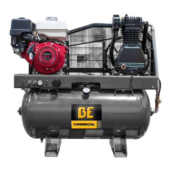
tROubLeshOOtING Compressor 1. Bad check valve. 1. Use IS 100 (30W) compressor won’t start in 2. Compressor has the wrong oil for cold weather conditions. cold weather grade of oil. 2. Move compressor to a warmer- 3. Control lines frozen. location. - Page 20 cOmpONeNts Please Note: The following diagram is intended for general reference of your compressor. Your unit may differ slightly from the unit shown below. For specific product information and breakdowns, visit BEPOWEREQUIPMENT.COM 9 10 11 12 13 AC1330HEBG2S & AC1330HB3000W feature a generator located between the air pump and the engine.
- Page 21 cOmpONeNts REF # Description Manual Tank Drain 30 Gallon 200 PSI Tank Tank Discharge Port Pilot Valve (Pressure Control) Pressure Gauge Throttle Control (Bull Whip) Drive Engine Drive Engine Pulley Drive Engine Pulley Mounting Hub Reciprocating Compressor Drive Belt Reciprocating Pump Discharge Line 250 PSI Discharge Safety Valve Reciprocating Pump Discharge Fitting Reciprocating Pump Air Filter Element &...
- Page 22 THE POWER YOU NEED. If you need assistance with the assembly or operation of this Compressor please call 1-866-850-6662...
Need help?
Do you have a question about the AC930HB and is the answer not in the manual?
Questions and answers