Table of Contents
Advertisement
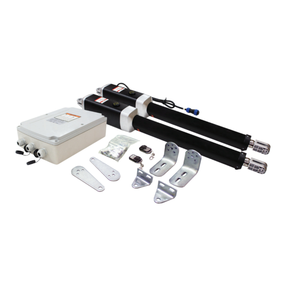
Double Swing Gate Opener
User Manual GTR058
Before starting we recommend watching the installation video that can be found at:
richmondau.com/product/gtr058-double-swing-gate-opener/
This video will give a detailed overview of the installation process and will serves as a useful aid during installation.
Instructions must be read before beginning installation. Please follow these instructions carefully,
incorrect installation could affect gate operation. If you require more information, please contact
your local Richmond Wheel & Castor Co branch.
AU: 1300 474 246
NZ: 0800 61 71 81
International: +613 9551 2233
For installation or troubleshooting assistance visit richmondau.com/gate-motor-support/
For accessories: please refer to the relevant accessory manuals for instructions on wiring them to the GTR058 motor.
1
GTR058 Installation Manual: Rev 22
Advertisement
Table of Contents

Related Manuals for Richmond GTR058


Summary of Contents for Richmond GTR058
- Page 1 AU: 1300 474 246 NZ: 0800 61 71 81 International: +613 9551 2233 For installation or troubleshooting assistance visit richmondau.com/gate-motor-support/ For accessories: please refer to the relevant accessory manuals for instructions on wiring them to the GTR058 motor. GTR058 Installation Manual: Rev 22...
- Page 2 GTR058 Installation Manual: Rev 22...
-
Page 3: Table Of Contents
Optional Installation: Setting the Gate as Push to Open Push to Open Installation Instructions & Wiring 27-30 Troubleshooting For accessories: please refer to the relevant accessory manuals for instructions on wiring them to the GTR058 opener. GTR058 Installation Manual: Rev 22... -
Page 4: General Safety
Any other use not specified in this documentation could damage the product and be dangerous. • Only use original parts for any maintenance or repair operation. Richmond Wheel & Castor Co declines all responsibility with respect to the automation safety and correct operation when other supplier’s components are used. -
Page 5: Parts List
M8 Nut (14 pcs) (2 pcs) M10x200 Bolt (8 pcs) M10x75 Bolt M10x30 Bolt M8x30 Washer (4 pcs) (2 pcs) (2 pcs) 12x40 Clevis Pin 12x30 Clevis Pin Hairpin Clip (2 pcs) (2 pcs) (4 pcs) GTR058 Installation Manual: Rev 22... -
Page 6: Technical Specifications
Single Arm - 1 gate opener used per gate Weight of Gate by Length Gate Length (m) Table 1 Dual Arm - 2 gate openers used on a heavier single gate Weight of Gate by Length Gate Length (m) Table 2 GTR058 Installation Manual: Rev 22... -
Page 7: Features
Reliable electromagnetism limit for easy adjustment • Comes with 2x pre-programmed remotes. Additional remotes can be purchased separately. • Can be equipped with a wide range of accessories, visit our website to see the full range of accessories available: richmondau.com/automatic-gate-openers-hardware/ GTR058 Installation Manual: Rev 22... - Page 8 Before you start: The GTR058 Swing Gate Automation Kits are suitable for gates up to 400kg per arm not exceeding 5m in length. Refer to Table 1 (page 6) to verify that your gate will be suitable. The motor arm uses a worm gear actuator to move your gate.
-
Page 9: Before You Start/Tools Required
If using ø20mm conduit the motor plug for gate motor 2 will need to be cut and wired back into the control box. Refer to the control board wiring diagram on page 25 (for pull to open) or page 27 (for push to open) We recommend getting an extra person to help with installation if possible GTR058 Installation Manual: Rev 22... -
Page 10: Gate Preparation
If the post is smaller than 6" diameter or square, it should be made of metal and set in cement. Fig 1 GTR058 Installation Manual: Rev 22... -
Page 11: Step 1 - Post Bracket Assembly
Secure in place with the M10 nut 2. Attach the Gate Bracket Assembly and Post Bracket Assembly to the opener by inserting the clevis pin. Temporarily secure the clevis pins using the hairpin clips as shown in Figure 3 Fig 3 GTR058 Installation Manual: Rev 22... - Page 12 Figure 4 below shows simple pivot bracket positioning to achieve a minimum of 95° range of motion. Note: Installing GTR058 on a Dual gate, steps 1-9 will apply to Gate Opener 1 (with 1.5m of cable), which should be mounted on the control box side of the property. You will need to repeat these steps for Gate Owener 2 (with 6m of cable).
-
Page 13: Step 2 - Set The Motor To Manual Mode
Bracket so that the gate arm is level. While holding the gate arm level, temporarily secure it with two C-clamps. Gate in the Open Position Post Bracket Assembly Clamp Clamp Gate Clamp Bracket Fence Gate Post Opener Fig 7 GTR058 Installation Manual: Rev 22... - Page 14 Clockwise until the arm begins to retract by hand. Fig 9 Do not proceed any further until you can achieve your full range of motion with everything positioned using clamps! GTR058 Installation Manual: Rev 22...
-
Page 15: Step 4 - Setting The Minimum Clearances
Please Note: Each swing arm contains an internal thread that may separate if overextended. If overextended a “Click” may be heard, to re-connect push and screw the arm Clockwise until the arm begins to retract by hand. Fig 10 GTR058 Installation Manual: Rev 22... -
Page 16: Step 5 - Affixing The Gate & Post Brackets
90° anti-clockwise. This puts the opener back into automatic mode. Pull to Open: Gate is Open Post Bracket Assembly bolted to fence post Gate Bracket bolted to gate cross member Fence Gate Post Opener Fig 13 GTR058 Installation Manual: Rev 22... -
Page 17: Step 6 - Mounting The Control Box
Step 07: Running the Motor Cable The GTR058 requires a power line for gate motor arm 2 to be run underground for connection to the control box. For safety the 6m cable needs to be run through conduit under your driveway. -
Page 18: Step 8 - Connecting The Gate Arm
Feed the cable through a gland, ensure enough cable length to wire the cable to the circuit board and retighten the gland to secure the cable. Refer to Figure 20 for details on how to connect optional accessories to the control board. GTR058 Installation Manual: Rev 22... -
Page 19: Step 9 - Adjusting The Travel Limit Switches
Each swing arm contains an internal thread that may separate if over extended. If overextended “Click” may be heard, to re-connect push and screw the sliding arm Clockwise until the arm begins to retract by hand. GTR058 Installation Manual: Rev 22... - Page 20 ‘9’ means that the Secondary Gate starts to open 9 seconds after the Primary Gate. Note: If you are fitting an electric lock to your swing gate. Please keep P3 set to 3 seconds or longer. GTR058 Installation Manual: Rev 22...
- Page 21 As per above description for P7 The value can be set between 1 – 50 seconds. ‘1’ means the Gate Arm 1 will stop after 1 second. Default setting is ‘40’ (seconds). There is no need to adjust this setting. GTR058 Installation Manual: Rev 22...
- Page 22 The digital display will show the status of both Gate Arms during operation. The first symbol refers to Motor 1, and the second symbol refers to Motor 2. During opening, the symbol will display ‘n’, and during closing the symbol will display ‘u’. GTR058 Installation Manual: Rev 22...
- Page 23 Please Note: The digital display will show the status of both Gate Arms during operation. The first symbol refers to Motor 1, and the second symbol refers to Motor 2. During opening, the symbol will display ‘n’, and during closing the symbol will display ‘u’. GTR058 Installation Manual: Rev 22...
-
Page 24: Pairing Remote Controls
To delete all paired remote controls, press and hold the button ‘LEARN’ for approx. 8 seconds. When the ‘LEARN’ LED turns off, all previously paired remote controls that will be deleted. (refer to fig 19) LED Display Learn Button Fig 19 Additional remotes can be purchased separately. Part number: GTR054 GTR058 Installation Manual: Rev 22... -
Page 25: Programming And Wiring
Programming and Wiring: Control Board Wiring Diagram: Fig 20 GTR058 Installation Manual: Rev 22... - Page 26 • Use the key to put the gate arms in manual mode and check opening/closing sequence by hand. • Discretion should be used to check more often, and after heavy wind and storms. GTR058 Installation Manual: Rev 22...
-
Page 27: Push To Open Installation Instructions & Wiring
Optional Installation: Operating the Gate as Push to Open: The GTR058 can be used as a Push-To-Open gate, you will need to use an Optional Push-To-Open Bracket (GTR059, sold separately) or mount the Post Bracket Assembly to the nearest side of the gate post opening. Note that in this configuration, the gate arm is retracted in the Closed position, and extended in the Open position. - Page 28 If the gate goes past your required closed position at full extension. This can be adjusted with the motor's limit switches. Refer to Pg 30 for instructions on adjusting this setting for a push to open installation. GTR058 Installation Manual: Rev 22...
- Page 29 If you cannot achieve your desired range of motion with the gate in manual mode refer back to the table on page 28 (Fig 26) and make any adjustments to the pivot bracket and gate bracket required to achieve full range of motion. Outside Property Inside Property Fig 27 GTR058 Installation Manual: Rev 22...
- Page 30 To adjust your final closed position of your Push to Open the centre, you will reduce the final gate adjust limit switch B towards the centre. Be careful not closed position of the gate. to move this switch much further to the right. Fig 29 GTR058 Installation Manual: Rev 22...
-
Page 31: Troubleshooting
NZ: 0800 61 71 81 International: +613 9551 2233 Richmond Wheel & Castor Co declines all responsibility for any consequences resulting from improper use of the product, or use which is different from that expected and specified in the present documentation.
Need help?
Do you have a question about the GTR058 and is the answer not in the manual?
Questions and answers