Table of Contents
Advertisement
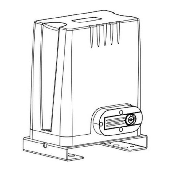
Sliding Gate Opener User Manual
Model: GTR064
Please Note: This motor runs on AC Power as standard but can also be operated by DC Battery Backup or Solar Power.
Gate in closed position
Gate in open position
Viewed from inside the property
WARNING
Instructions must be read before beginning installation. Please follow these instructions carefully, incorrect
installation could affect gate operation. If you require more information, please contact
Richmond Wheel & Castor Co on 1300 474 246
When mounting and positioning the motor ensure that the power cable is unplugged. The motor cover will need to
be removed to mount the motor to the mounting plate. Any changes to the settings of the gate motor can only be
made by a licensed electrician.
1
Rev 20A
Advertisement
Table of Contents

Related Manuals for Richmond GTR064


Summary of Contents for Richmond GTR064
- Page 1 If you require more information, please contact Richmond Wheel & Castor Co on 1300 474 246 When mounting and positioning the motor ensure that the power cable is unplugged. The motor cover will need to be removed to mount the motor to the mounting plate.
- Page 2 Optional Accessories Available: Additional Remotes (GTR179): Spare/Additional remotes for the automatic gate kit, these will need to be paired to the motor. Wireless Keypad (GTR180): Allows secure access through the gate used with a user set code. Hard Wire Keypad (GTR199): Allows secure access through the gate used with a user set code. Warning Light (GTR198): Alerts people near the gate and users that the gate is in operation.
-
Page 3: Table Of Contents
Contents: Gate Opening Default Setting Information…………………………………….………4 General Safety………………………………………………….………………...…….…..5 Parts List…………………………………………………….………………………………6 Technical Specifications………………………………………….………………………7 Motor Installation Before you start……………………………………………………….………….…8 Tools Required / Example Sliding Gate Setup…………….…….………………9 Step 1 – Gate Preparation……………………………………...…...……………10 Step 2 – Motor Pad Footing.………………………………...………………...…10 Step 3 - Motor Position Installation………….………………..……………….…11 Step 4 –... -
Page 4: Gate Opening Default Setting Information
Gate Opening Default Setting Information: The gate motor will open the gate to the right-hand side as its default setting (refer to fig 1). Default operation: Motor mounted on the right-hand side Fig 1 Before Installing: Test the motor by plugging it into a power source and pressing the remote. You will see the motor cog turn. -
Page 5: General Safety
Any other use not specified in this documentation could damage the product and be dangerous. • Only use original parts for any maintenance or repair operation. Richmond Wheel & Castor Co declines all responsibility with respect to the automation safety and correct operation when other supplier’s components are used. -
Page 6: Parts List
Parts List: Picture Name Quantity Main motor Motor Mounting Plate Manual release keys (These keys are needed during power outage, keep on hand) Remote controls (factory paired to motor) Gate Warning Signage (must be fitted to gate) In the accessories box you will find the items below: Magnetic limit travel stops 1 small bracket... -
Page 7: Technical Specifications
Technical Specifications: Model GTR064 Power supply 240V/50Hz Motor power 170W Gate moving speed 16-18m/min Maximum weight of gate 1000 Kg Remote control distance Up to 30m Remote control mode Single button mode Limit switch Magnetic limit switch Noise Up to 58dB... -
Page 8: Motor Installation
Power Supply: The GTR064 requires 1 x 10Amp AC240V 50Hz power supply (RCD Protected Weatherproof PowerPoint). The GTR064 comes complete with a power lead and plug that is 1m long. If you do not have a suitable RCD protected weatherproof power point within 1m of the gate motor you will need to consult a licenced electrician . -
Page 9: Tools Required / Example Sliding Gate Setup
Socket and Spanner Set • Phillips Head Screwdriver Example Sliding Gate Setup: Gate Track and Gate Guide Gate End Gate Track Wheels Rollers Catch Stopper If you require any gate hardware, contact Richmond Wheel & Castor Co or an authorised reseller. Rev 20A... -
Page 10: Step 1 - Gate Preparation
Please ensure that the motor power cable is not plugged in at any stage before Step 8 Step 1 - Gate Preparation Before Adding Your Sliding Gate Motor: • Ensure that the sliding gate is correctly installed. • The gate is horizontal and level and the gate can glide back and forth smoothly when moved by hand before installing the Automatic Gate Opener. -
Page 11: Step 3 - Motor Position Installation
Step 3 - Motor Position installation: • Insert the key and open the manual release bar to put the motor into manual mode, and check that the motor cog rotates freely by hand (As per Fig 15). • Place the motor and motor mounting plate on the concrete pad. •... -
Page 12: Step 5 - Fitting The Mounting Plate & Motor
Step 5 - Fitting mounting Plate & Motor: • Fit motor mounting plate back into place and fit and tighten anchor bolts (as per figures 7 and 8). • Fit motor back on mounting plate, ensuring the power cord is positioned into the end slot of the mounting plate in the direction of the power point, making sure there are no pinch points (as per fig 9). -
Page 13: Step 6 - Gear Rack & Motor Alignment
Please ensure that the motor power cable is not plugged in at any stage before Step 8 Step 6 - Gear Rack & Motor Alignment: • Insert the key and open the manual release bar to put the motor into manual mode, and check that the motor cog rotates freely by hand (as per fig 15). - Page 14 Fig 16 Please Note: The warning signage provided (Part 5) must be displayed on the frame of your automatic gate at all times. Fig 17 Rev 20A...
-
Page 15: Step 7 - Limit Travel Stops
Step 7 - Magnetic limit switch stops Installation: Included in your gate motor kit are two magnetic limit travel stops which must be fitted to the gear rack on your gate to ensure safe operation. The magnetic limit travel stops are designed to set the desired opening and closing position of your gate. - Page 16 Note: The default setting is right side open. Magnetic Limit Travel Stop B (LARGER) should be positioned at the closed position. Magnetic Limit Travel Stop A (SMALLER) should be positioned at the open position. Fig 21 Fig 22 Fig 23 Fig 24 If the limit travel stops are more...
-
Page 17: Step 8 - Powering The Motor
• Soft start/soft stop function - The GTR064 is set by default to provide the soft start/soft stop function. We recommend this default position is always maintained. Your motor is now set up for basic remote-control operation. To set further functions... -
Page 18: Step 9 - Testing The Limit Travel Stops
Step 9 – Testing and Adjusting the Magnetic Limit Travel Stops: Testing the closed position • Ensure motor is plugged in as per step 8 and the gate is in the open position. • Press remote (remotes included in kit are factory paired to the motor). The gate will begin to close. -
Page 19: Programming And Wiring
Programming and Wiring: Control board wiring diagram 01 Any works to the 240V AC must only be performed by a licensed electrician. Ensure power is off before any modifications are made. Fig 27 Rev 20A... - Page 20 Programming and Wiring: Control board wiring diagram 02 Please refer to page 24 & 25 for added description of terminals Fig 28 Rev 20A...
- Page 21 Transformer Power Input Connection: WARNING: Do not touch 240VAC. All works to mains power must be conducted by a licensed electrician. Fig 29 Live parts behind cover DO NOT TOUCH All works to mains power must be conducted by a licensed electrician.
-
Page 22: Dip Switch Adjustment
Dip Switch Adjustment: All changes to these settings must be completed by a licensed electrician Number Description Automatic Close Function 1 ON 2 OFF: automatic close delay time is 3s. 1 OFF 2 ON: automatic close delay time is 10s. 1 ON 2 ON: automatic close delay time is 30s. -
Page 23: Further Settings And Programming
Further Settings & Programming: All changes to these settings must be completed by a licensed electrician VR1: Total Working Time Adjustment Rotate clockwise to increase, counter-clockwise to decrease. Total time can be set to 10 seconds minimum, and 90 seconds maximum. The default setting is at maximum. - Page 24 All changes to these settings must be completed by a licensed electrician J1 Terminal: Terminal 5: Common (Ground). Terminal 6: Photocell input (Normally Closed). If no photocell is fitted use jumper between terminals 5 & 6. Terminal 7: Extra power input +24VDC. J7 Terminal: Terminal 1: Optional External Open Push Button Switch.
- Page 25 All changes to these settings must be completed by a licensed electrician J2 Terminal: Factory Fitted (pre-wired) Connect to 24VAC power from transformer. BAT Terminal: Battery Backup Terminal. J4 Terminal: Factory Fitted (pre-wired) DC motor wire connection (Red wire to top,black wire to bottom). J8 Terminal: 24V DC warning light connection.
-
Page 26: Connecting Infrared Photocells
Connecting Infrared Photocells: The below steps must be completed by a licensed electrician Richmond highly recommend the use of infrared photocells as an additional safety feature. While closing, if infrared beam of the photocell is blocked, the gate will stop and reverse immediately, to protect user and property security. -
Page 27: Battery/Solar Connection
Note that performance may vary according the amount of sunlight per day, and condition of the batteries. To install battery backup and/or solar power, refer to the Figures 11 and 12 below. Note: For 100% Solar requirements please contact Richmond. Battery Part Number: GTR160... -
Page 28: Connecting Solar Power (Sold Separately)
Solar Panel Connection Solar charge Controller Solar panel Storage battery CHARGE LOAD BATTERY + - + - + - Battery Part Number: GTR160 Control board Fig 28 Rev 20A... -
Page 29: Maintenance
Maintenance: Under normal operation, the gate should be checked every 6 months: • Lubricate shafts and sprockets • Check and tighten anchor bolts • Check for loose and corroded wires. • Check the earth wire (green/yellow) is firmly attached to the housing with the screw. This should be checked by a licensed electrician. -
Page 30: Troubleshooting
If cannot be easily is pressed, but opened, re-set up. motor makes a 2. Contact Richmond Wheel & Castor Co for noise. replacement PCB. Gate does not stop 1. The gate direction is... -
Page 31: Clearing And Pairing Remotes
LED flashes ON. paired. Technical Support For support or assistance with installing your gate motor, ring your local Richmond Wheel & Castor Branch on 1300 474 246. For detailed technical support, ring our Engineering Department on 03 9551 2233. Richmond Wheel & Castor Co declines all responsibility for any consequences resulting from improper use of the product, or use which is different from that expected and specified in the present documentation. -
Page 32: Additional Drawings And Diagrams
Additional Drawings and Measurements: Magnetic Limit Switch Sensor (located beneath the motor cover) Rev 20A...
Need help?
Do you have a question about the GTR064 and is the answer not in the manual?
Questions and answers