Table of Contents
Advertisement
Quick Links
BROBO GROUP (AUST) PTY. LTD.
☏
��
PRODUCT AND MAINTENANCE MANUAL
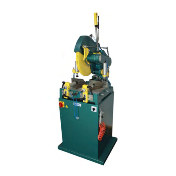
MANUAL NON-FERROUS CUTTING SAW
YOUR BROBO DISTRIBUTOR IS:
___________________________________________________________________________________________
Precision Drilling Machines Tapping Machines Multi-Head Drills Tool Grinders
Accessories Riveting Machines Pedestal Grinders Metal Cutting Saws Linishers
8 Fowler Rd, Dandenong South
Victoria 3175, AUSTRALIA.
+ 61 3 9794 8751
+ 61 3 9794 8792
MODEL No. TNF 115 (SERIES 2)
Tool Post Grinders Machine Vices Special Production Equipment
©
��
info@brobo.com.au
www.brobo.com.au
A.C.N.
098 264 316
A.B.N. 42 098 264 316
Advertisement
Table of Contents

Related Manuals for Brobo TNF 115 2 Series


Summary of Contents for Brobo TNF 115 2 Series
- Page 1 © A.C.N. 098 264 316 A.B.N. 42 098 264 316 BROBO GROUP (AUST) PTY. LTD. 8 Fowler Rd, Dandenong South Victoria 3175, AUSTRALIA. �� ☏ + 61 3 9794 8751 info@brobo.com.au �� + 61 3 9794 8792 www.brobo.com.au PRODUCT AND MAINTENANCE MANUAL MANUAL NON-FERROUS CUTTING SAW MODEL No.
- Page 2 OPERATING MANUAL FOR BROBO GROUP MANUAL NON-FERROUS CUTTING SAW TNF115 TECHNICAL SPECIFICATION CHAPTER 1: Installation of the Machine Unpacking & Handling the Machine Parts Checklist Minimum Requirements Anchoring the Saw Connection to Power Source CHAPTER 2: Safety & Accident Prevention Operation of the Machine 2.1.1.
-
Page 3: Technical Specification
870 mm Dimensions L x W x H 670 x 850 x 1700 mm Packaged L x W x H 1140 x 1140 x 1700 mm Roller Conveyor 300 x 30 x 20 mm WEIGHT 167 Kg Brobo Group brobo.com.au... - Page 4 CUTTING RANGE CHART 90˚ 100 mm 45˚ 100 mm 90˚ 100 mm 45˚ 100 mm 90˚ 100 x 190 mm 45˚ 100 x 130 mm Brobo Group brobo.com.au...
-
Page 5: Chapter 1 - Installation Of The Machine
Upon receiving the Brobo Group TNF115 Series 2, the machine should be standing upright & positioned centrally on top of a wooden pallet. While the machine is situated on the pallet, position the forklift arms under the pallet between the runners, keeping in mind that the machine is head heavy. - Page 6 Each saw model has an inbuilt safety system to protect it against voltage variations. However, for the machine to perform efficiently, ensure that the saw unit operates within 10% limits of the recommended voltage of the motor. Brobo Group brobo.com.au...
-
Page 7: Required Working Area
For added stability, it is strongly recommended that the machine stand is fastened to the floor by using loxins (not provided). Required Working Area It is recommended that A & B is more than 1.5m Figure 2. Saw TNF115 S2 Length Stop with Conveyor Brobo Group brobo.com.au... -
Page 8: Connection To Power Source
& connect it accordingly to the corresponding voltage supply. d) If the dual motor is requested, the motor is always connected to the higher voltage, unless otherwise specified prior to the order being placed. Brobo Group brobo.com.au... -
Page 9: Chapter 2 - Safety & Accident Prevention
CHAPTER 2 - Safety & Accident Prevention Brobo Group TNF115 Series 2 has been designed & manufactured in accordance with Australian Standards. It is HIGHLY RECOMMENDED that the instructions & warnings contained in this chapter be carefully followed for correct usage of the machine. -
Page 10: Noise Level
Value of the sonorous level in the working position measured Lmp= 91,1 dB (A) Factor of environmental correction K= 1 dB (A) Medium value of the correct sonorous level Lpc= 85,3 dB (A) Value of sonorous level in the correct working position Lpc= 90,1 dB (A) Brobo Group brobo.com.au... -
Page 11: Power Supply
IEC Standards Part 195: Earthing & Protection Against Electric Shocks 1998. Position of the Operator The user controlling the machine saw operations must be positioned as shown in figure 5 below. Figure 5. Correct Position for Operating Saw Unit Brobo Group brobo.com.au... -
Page 12: Advice For The Operator
Always keep the workplace are as clean as possible. Remove equipment, tools or any other objects from the cutting zone. Support the workpiece on both sides of the machine to prevent it falling or jamming during the cutting cycle. Brobo Group brobo.com.au... - Page 13 This could damage the blade, the specimen or be a cause for potential injury to the operator. Always turn off the machine before carrying out any repair work. Consult the Brobo Group Engineering Department in the country in which the machine was initially purchased. Brobo Group...
-
Page 14: Machine Safety Devices
& safely. The following standards listed in section 2.4.1, which are applicable to the Brobo Group TNF115 Series 2, are those specified by the EEC Committee that governs the safety of machinery, health & safety at work, personal protection &... -
Page 15: Chapter 3 - Main Functions & Operation Of The Machine
The saw is held in the safety rest position by a locking system & assisted back to its rest position by a return spring Figure 7. Saw Safety Guard & Locking System Brobo Group brobo.com.au... - Page 16 Clamp Adjustment: Adjustment is done by first releasing the levers & then moving the cylinder holders to the left or right or moving the cylinders backwards & forwards. The cylinders & the holders themselves move independently from each other. Figure 11. Vice Clamp Brobo Group brobo.com.au...
-
Page 17: Preparation For Operation
3.2. Preparation for Operation The following procedure is recommended for the correct cutting using the Brobo Group TNF115 Series 2 WARNING – SAFETY GEAR Protective clothing, safety glasses and gloves should always be worn while loading parts, operating the machine, or undertaking any maintenance work on the saw. -
Page 18: Operation Recommendations
As a rule of thumb the softer the component, the faster the rate of speed. Note that for non-ferrous materials such as brass, copper, aluminium etc. require much faster speeds than Ferrous Metal Cutting Saws CHAPTER 4 - Drawings, Layouts, Assembly & Spare Parts Brobo Group brobo.com.au... - Page 19 NOTE MINIMUM 600MM ALL AROUND SAFE SPACE FOR OPERATING ZONE TITLE: TNF 115 S2 MAIN BROBO GROUP ISSUED DATE 07.02.2019 DIMENSIONS DRAWN BY ANH Address : 8 Fowler Rd, Dandenong VIC 3175 https://brobo.com.au/ SCALE:NTS SHEET 1 OF 4...
- Page 22 TCT Saw Blades – General Information Tooth Geometry of TCT Saw Blades triple chip tooth alternating with fl at fl at tooth tooth FZ N fl at tooth with negative hook angle triple chip tooth alternating with fl at TFZ N tooth with negative hook angle fl...
- Page 23 TCT Saw Blades – General Information Here are some useful formulas to help you calculate the correct number of teeth on saw blades: D x π h x 1,45 Key: [mm] – tooth pitch [mm] – thickness of the work piece [–] –...
- Page 24 Date: 29.11.2009 Author: Bratislav EXPLOSION VIEW MOST M Sklop glave E-03/05 Page: 1 /2...
- Page 25 Date: 29.11.2009 Author: Bratislav EXPLOSION VIEW Parts List Parts List ITEM QTY PART NUMBER TITLE DESCRIPTION ITEM QTY PART NUMBER TITLE DESCRIPTION SAFETY GUARD DIN 912 - M8 x 25 03M/05 Cylinder Head Cap Screw DIN 125 - A 8,4 Washer 02-27/05 SUPPORT...
- Page 26 Date: 29.11.2009 Author: Bratislav EXPLOSION VIEW 126 127 MOST M Sklop suporta E-02/05 Page: 1 /2...
- Page 27 Date: 29.11.2009 Author: Bratislav EXPLOSION VIEW Parts List ITEM PART NUMBER TITLE DESCRIPTION CLAMPING TALBE 02/05 13-01/06 ROTARY TABLE 02-25/06 TILT ADJUSTMENT SUPPORT 14-01/06 CENTER SHAFT 15-01/06 NUT M30x2 23/06 QUICK RELEASE KNOB DIN 125 - A 8,4 Washer DIN 912 - M8 x 30 Cylinder Head Cap Screw 04-01/06 WEAR PLATE (LH)
- Page 28 Date: 29.11.2009 Author: Bratislav EXPLOSION VIEW MOST, ZETA Sklop šnapera E-04/05 Page: 1 /2...
- Page 29 Date: 29.11.2009 Author: Bratislav EXPLOSION VIEW Parts List ITEM PART NUMBER TITLE DESCRIPTION 03-23/06 01-23/06 Opruga šnapera SPRING ISO 8752 - 3 x 30 Spring-Type Straight Pin Ručka M10 HANDLE MOST, ZETA Sklop šnapera E-04/05 Page: 2 /2...
- Page 30 SUBJECT TO RECALL. REPRODUCTIONS OF THIS DRAWING IN ANY MATERIAL Det. Part No. Qty. Name & Material Sheet Remark FORM ARE RESERVED TO BROBO WALDOWN (AUST) Raw Mat. #. Drawn Checked Scale Pty. Ltd. O.Dj. S.R. BROBO WALDOWN Sub Ass'y UNDER COPYRIGHT LAW.
- Page 31 NOT SOLD, BUT LENT AND IS SUBJECT TO RECALL. REPRODUCTIONS OF THIS DRAWING IN ANY MATERIAL FORM ARE RESERVED TO BROBO WALDOWN (AUST) Pty. Ltd. UNDER COPYRIGHT LAW. GR - CAM SWITCH K1 - CONTACTOR ( COIL 230V) 3~M - 3 PHASE MOTOR 1.5kW PR - ELECTRO PNEUMATIC SWITCH Det.
-
Page 32: Chapter 5 - Adjustments For The Saw Unit
5) Using a 36mm spanner, loosen the blade counter plate screw in a clockwise direction. Keeping in place the contrast spanner release the screw & remove the counter plate to be able to remove the blade from the shaft. Figure 12. Adjustment the Saw Brobo Group brobo.com.au... -
Page 33: Lubrication Adjustment
In addition, rags soaked in oil should not be burned. Do not pour oil down the drain, which would ultimately contaminate the water supply & pollute the environment. For firefighting purposes, either use CO2, dry chemical or foam retardant to extinguish the flames. Brobo Group brobo.com.au... -
Page 34: Chapter 6 - Maintenance & Selection Of Consumables
6.1. Role of the Operator The person operating & maintaining the Brobo Group TNF115 Series 2 must familiarise themselves with these instructions for their own safety & that of the others, in addition to safeguarding the production of the machine. - Page 35 & the filter should be drained frequently. 6) Ensure that the machine performs cuts perpendicular to the work surface. If not, contact Brobo Group engineering department. 7) Test that the blade is at right angles to the workpiece back fence.
-
Page 36: Chapter 7 - Appendix
CHAPTER 7 - Appendix A.C.N. 098 264 316 A.B.N. 42 098 264 316 BROBO GROUP (AUST) PTY. LTD. 8 Fowler Rd, Dandenong South, 3175 Victoria, AUSTRALIA. Tel: 61 3 9792 9944 Email: info@brobo.com.au Fax: 61 3 9791 9955 Website: www.brobo.com.au... - Page 37 This warranty is given by Brobo Group Pty Ltd, ABN: 42 098 264 316 Address: 8 Fowler Rd, Dandenong, VIC 3175 ✆...
Need help?
Do you have a question about the TNF 115 2 Series and is the answer not in the manual?
Questions and answers