Table of Contents
Advertisement
BROBO GROUP (AUST) PTY. LTD.
8 Fowler Rd, Dandenong, 3175
PO BOX 4274 Dandenong Sth, 3164
Victoria, AUSTRALIA.
Tel:
61 3 9794 8751
Fax: 61 3 9794 8792
PRODUCT AND MAINTENANCE MANUAL
OHS SERIES METAL SAWS
MODEL No. S315D, S350D, S400B / Serial No's. C 29680~
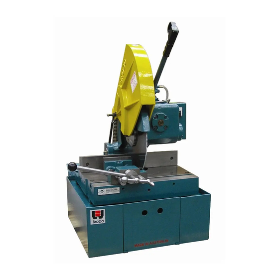
Bench Mount Unit
YOUR BROBO DISTRIBUTOR IS:
Precision Drilling Machines Tapping Machines Multi Head Drills Tool Grinders
Tool Post Grinders Machine Vices Special Production Equipment
Accessories Riveting Machines Pedestal Grinders Metal Cutting Saws Linishers
A.C.N.
A.B.N. 42 098 264 316
Email:
info@brobo.com.au
Website:
www.brobo.com.au
Floor Mount Unit
098 264 316
Quality
Endorsed
Company
ISO 9001 Lic. 10292
SAI GLOBAL
Advertisement
Table of Contents
Troubleshooting

Related Manuals for Brobo S315D, S350D, S400B


Summary of Contents for Brobo S315D, S350D, S400B
- Page 1 Fax: 61 3 9794 8792 Website: www.brobo.com.au PRODUCT AND MAINTENANCE MANUAL OHS SERIES METAL SAWS MODEL No. S315D, S350D, S400B / Serial No’s. C 29680~ Bench Mount Unit Floor Mount Unit YOUR BROBO DISTRIBUTOR IS: Precision Drilling Machines Tapping Machines Multi Head Drills Tool Grinders ...
- Page 2 OPERATING MANUAL FOR BROBO GROUP MANUAL METAL CUTTING SAWS TECHNICAL SPECIFICATION CHAPTER 1: Installation of the Machine Unpacking and Handling the Machine Parts Checklist Minimum Requirements Anchoring the Saw Connection to Power Source CHAPTER 2: Safety and Accident Prevention Operation of the Machine 2.1.1.
-
Page 3: Technical Specification
This chart is issued as a guide only. Many other factors would attribute to the cutting performance of both the saw blade and the cutting saw machine. BROBO GROUP Pty. Ltd. will not accept any responsibility for the blade selection and/or machine breakages or unsatisfactory cutting performance of both the blade and/or the machine as a direct result of the selection. - Page 4 TABLE 4. Blade Spindle RPM VICE CLAMPS Manual Vice Clamping Range (mm) 0 - 135 (145mm w/o wear plates) Air Requirements: Air Consumption (L): Clamp Working Pressure (kPa): Maximum Pressure (kPa): Pneumatic Stroke (mm): Clamping Force (N): TABLE 5. Vice Clamps Brobo Group...
- Page 5 CUTTING RANGE Cross Cutting Range (mm) Sectional Angle S315 S350 S400 Profile 3 6/8" 4 4/8” 5 1/8” 90 3 6/8" 4 3/8” 4 6/8” 45 85 85 3 3/8" 3 3/8" 100 100 3 7/8" 3 7/8" 110 ...
- Page 6 Upon receiving the S315/S350/S400 Series Metal Cutting Saw, the machine should be standing Brobo Group upright and positioned centrally on top of a wooden pallet. While the machine is situated on the pallet, position the forklift arms under the pallet between the runners, keeping in mind that the machine is head heavy. Move the entire unit to an accessible area as close as possible to the final location.
-
Page 7: Minimum Requirements
Each saw model has an inbuilt safety system to protect it against voltage variations. However, for the machine to perform efficiently, ensure that the saw unit operates within 10% limits of the recommended voltage of the motor. Brobo Group... - Page 8 Figure 2. BENCH MODELS (Fig. 2.1 & 2.2) FLOOR MODELS (Fig. 2.3 & 2.4) FRONT OF MACHINE FRONT OF MACHINE Figure 2.1 Figure 2.3 FRONT OF MACHINE FRONT OF MACHINE Figure 2.2 Figure 2.4 Figure 2. Anchoring Hole Locations Brobo Group...
- Page 9 If dual motor is requested, the motor is always connected to the higher voltage, unless otherwise specified prior to order being placed. Brobo Group...
- Page 10 4) Ensure that all electrical leads and cables (including supply leads) are maintained in a good condition and away from sharp objects. All leads should be replaced if cut, sliced or damaged in any way. Brobo Group S315/S350/S400 Series Metal Cutting Saw is now ready for use.
-
Page 11: Operation Of The Machine
CHAPTER 2 - Safety and Accident Prevention S315/S350/S400 Series Metal Cutting Saw has been designed and manufactured in Brobo Group accordance to Australian Standards. It is HIGHLY RECOMMENDED that the instructions and warnings contained in this chapter be carefully followed for correct usage of the machine. -
Page 12: Power Supply
IEC Standards Part 195: Earthing and Protection Against Electric Shocks 1998. Position of the Operator The user controlling the machine saw operations must be positioned as shown in the figure 5 below. Figure 5. Correct Position for Operating Saw Unit Brobo Group... - Page 13 Always keep the workplace are as clean as possible. Remove equipment, tools or any other objects from the cutting zone. Support the work piece on both sides of the machine to prevent it falling or jamming during the cutting cycle. Brobo Group...
- Page 14 This could damage the blade, the specimen or be a cause for potential injury to the operator. Always turn off the machine before carrying out any repair work. Consult the Brobo Group Engineering Department in the country in which the machine was initially purchased. Brobo Group...
-
Page 15: Machine Safety Devices
EEC Directive No. 80/1107; 83/477; 86/188; 88/188; 88/642 - Protection of workers against risks caused by exposure to physical, chemical and biological agents in workplace EEC Directive No. 73/23 and Special EEC Directives No. 89/654; 89/655 - Improvements in health and safety at work Brobo Group... -
Page 16: Cutting Head
It also functions as a safety device to protect the operator from any broken tooth, swarf or high-velocity particles that might be dislodged by the cutting process. Figure 6. Saw Safety Guard Brobo Group... - Page 17 AT any time the “Dead Man” trigger is activated the saw will run. 3.1.5. Manual Vice Clamp Figure 8. Standby Lamp The manual vice clamp lever allows speedy clamping of material with ergonomically designed clamp lock. Figure 9. Manual Vice Clamp Brobo Group...
- Page 18 7) Machine is ready for the next cutting cycle. WARNING - BLADE JAMMING If the saw blade jams during a cut, engage the EMERGENCY STOP immediately. Remove the part, check that the blade is not damage and if need be, replace the blade. Brobo Group...
- Page 19 If these are the majority of materials cut, a NF Series machine should be considered. Brobo CHAPTER 4 - Drawings, Layouts, Assembly and Spare Parts Brobo Group...
- Page 25 ONE PHASE THREE PHASE COMPONENT / SCHEMATIC / WIRING DIAGRAMS FOR CONNECTION FOR 1 PHASE OR 3 PHASE CIRCUIT...
- Page 27 ELECTRICAL DIAGRAM 2 Speed Switch (1-0-2)
- Page 28 NOTE MINIMUM 600MM ALL AROUND SAFE SPACE FOR OPERATING ZONE TOP VIEW ISSUED DATE 25.08.2017 SIDE VIEW DRAWN BY ANH BROBO GROUP COLD SAW TITLE: MAIN DIMENSIONS SCALE:NTS SHEET 1 OF 1...
- Page 29 Deadman Trigger 9301040 Assembly Screw Soc Hex HD Cap 8705050 M6x12 9554030 Spring Bracket Upper Gearbox Gearbox Assembly ITEM NO. PART NO. DESCRIPTION QTY. ISSUED DATE 03.11.2017 DRAWN BY ANH BROBO GROUP COLD SAW TITLE: ASSEMBLY SCALE:NTS SHEET 1 OF 1...
- Page 30 Coolant Tap 8705050 Screw Soc Hex HD Cap M6x12 9025800 Sawblade 350 ISSUED DATE 03.11.2017 DRAWN BY ANH 9504090 Spindle Counter Plate BROBO GROUP 8715080 Roll Pin 8x25 8735090 M16 x 40 TITLE: STANDARD GEARBOX 9304017 Pin - Coolant Pump...
- Page 31 PART NUMBER DESCRIPTION QTY. 9615490 XLR Socket PD5367 Electrical Box Assembly 1 = RED 2 = YELLOW N = BLACK ISSUED DATE 25.07.2017 DRAWN BY ANH BROBO GROUP TITLE: DEADMAN TRIGGER ASSEMBLY PART NO. 9301040 SCALE:NTS SHEET 1 OF 1...
-
Page 32: Vice Assembly
8735380 Rollpin ⌀8x40 LG 9314280 Vice Block Clamp 8705980 Rollpin ⌀6x16 LG 9405090 Compression Spring 8705460 Screw Flat HD M5x8 LG 8726100 Socket Button Head Cap Screw M6x16 ISSUED DATE 08.11.2017 BROBO GROUP TITLE: STANDARD MANUAL VICE ASSEMBLY PART NO. 9311060 SCALE:1:5... - Page 33 8726100 Socket Button Head Cap Screw M6x16 9302260 Extension Arm Block 9302250 Side Extension Arm 8725470 Flat Washer ⌀10 8725960 Screw Soc Hex HD Cap M10x40 8705490 Set Screw M8x16 ISSUED DATE 08.11.2017 BROBO GROUP TITLE: DUAL ARM VICE ASSEMBLY PART NO. 9301950 SCALE:1:5...
-
Page 34: Changing The Blade
10) If optional devices are supplied, mount the stock support and rollers on either side of the clamping table. Normally stock should feed from left to right, but it can be feed from the right to left, if required. Brobo Group... -
Page 35: Adjusting The Cutting Angle
The back jaw wear plates on the S315/S350/S400 Series Metal Cutting Saw are typically fitted in Brobo Group the following manner. For angular cutting, the wear plates should be repositioned to provide the maximum support on one side and clearance on the other (Figure 11). - Page 36 If splashed by hot oil, immediately run cold water over the burn area and apply first aid burn treatment. If the Brobolube delivery line breaks or becomes disconnected during operation, ensure that the air supply to the system is disconnected before repairing the problem. Brobo Group...
- Page 37 In addition, rags soaked in oil should not be burned. Do not pour oil down the drain, which would ultimately contaminate the water supply and pollute the environment. For firefighting purposes, either use CO2, dry chemical or foam retardant to extinguish the flames. Brobo Group...
-
Page 38: Maintenance Requirements
The person operating and maintaining the S315/S350/S400 Series Metal Cutting Saw must Brobo Group familiarise themselves with these instructions for their own safety and that of the others, in addition to safeguarding the production of the machine. Responsibility must be taken by the user on the general maintenance and up keeping of the unit as specified in this chapter, with particular emphasis on: ... - Page 39 Coolant level would expect to naturally decrease over time due to natural evaporation. Use premium quality coolants such as CoolTech 500 or SlideTech 68. Coolant is available from BROBO GROUP Pty. Ltd. in 2 litre & 20 litre packs (Part No. 9301570 & 9501080): Concentrate, Ratio 1:20 4) Lubricate the saw head pivot shaft and rotary table regularly (after every 40 hours of operation, or weekly) with an NLGI 2 extreme pressure grease, Shell Alvania No.1 grease or equivalent.
- Page 40 With a new blade, it is necessary to start cutting at half feeding speed. After a normalising period (cutting surface about 300cm for hard materials and 1000cm for softer materials), both cutting and feed speeds can be brought up to normal values. Brobo Group...
- Page 41 Teeth in contact with material before commencing the cut Check the coolant level and clean piping and nozzles Insufficient coolant Specimen vibrates in the vice; check that the vice clamps are position correctly and the clamping pressures Excessive vibrations are adequate Brobo Group...
- Page 42 Metal Cutting Saw and the recommended troubleshooting procedures to undertake to rectify the situations. If the solutions provided do not resolve the problem, or the problem identified differs from those listed, immediately contact Brobo Group engineering department. PROBLEM IDENTIFIED DIAGNOSIS...
- Page 43 A.C.N. 098 264 316 A.B.N. 42 098 264 316 Quality BROBO GROUP (AUST) PTY. LTD. Endorsed Company 8 Fowler Rd, Dandenong, 3175 ISO 9001 Lic. 10292 PO BOX 4274 Dandenong Sth, 3164 Standards Australia Victoria, AUSTRALIA. Tel: 61 3 9792 9944 Email: info@brobo.com.au...
- Page 44 APRIL 2009 C O N T E N T S HAZARD ................ ...
- Page 45 SCOPE A risk assessment program of plant items was commenced on behalf of Brobo Pty. Ltd. Dandenong South during March 2009. The assessment was commissioned by Mr David Golic. Plant items assessed were located within the manufacturing facility located at 66-68 Williams Rd. Plant assets inspected were as per the Operating Manual for the OHS Series S315, 350, 400 S SCV Metal Cutting Saws, Sn’s.
- Page 46 Unusual but possible Remotely Possible Conceivable Practically Impossible Exposure Consequence: Disaster Almost Certain Quite possible Unusual but possible Remotely Possible Conceivable Practically Impossible Exposure Consequence: Very Serious Almost Certain Quite possible Unusual but possible Remotely Possible Conceivable Practically Impossible Brobo Group...
- Page 47 Unusual but possible Remotely Possible Conceivable Practically Impossible Exposure Consequence: Substantial Almost Certain Quite possible Unusual but possible Remotely Possible Conceivable Practically Impossible Exposure Consequence: Minor Almost Certain Quite possible Unusual but possible Remotely Possible Conceivable Practically Impossible Brobo Group...
- Page 48 Immediate cessation of work, isolation of area and corrective action required High Immediate corrective action required Substantial Should receive attention within specified time Moderate Should be dealt with within specified time but not an emergency Risk is acceptable Brobo Group...
- Page 49 A review schedule must be introduced that will enable management and the responsible people to evaluate the performance and the quality of the controls. They also need to be able to determine if any further risks have been created as a result of the introduced control. Brobo Group...
- Page 50 B r o b o P t y . L t d . D a n d e n o n g S o u t h P l a n t R i s k A s s e s s m e n t R e p o r t HAZARD, RISK, CONTROL REPORT M a k e : B r o b o C o l d C u t S a w M o d e l : S / S C V 3 1 5 A / D , 3 5 0 / D , 4 0 0 / B...
- Page 51 D a n d e n o n g S o u t h P l a n t R i s k A s s e s s m e n t R e p o r t Brobo Group...
- Page 52 (saw blade : 3:3:4 must be completely guarded when in standby, existing guard does not adequately CORE prevent access to saw blade while in standby position). Brobo Group...
- Page 53 M.S.D.S.. Display M.S.D.S for all chemicals on display board. CORE Stability of Saw Collapse of pedestal/stand during use. Operator Securely fasten base of pedestal to floor with dyna-bolts or similar / Fit on suitable pedestal / Stand. injuries, plant damage. pedestal. : 4:4:4 CORE Brobo Group...
- Page 54 This is to certify That an AS 4360 Risk Assessment has been completed on the Brobo S315 A/D, S/SCV 350 D, S/SCV 400/B OHS Series Metal Saws Serial No's. *C29680 ~ (*Subject to limitations) Risk Control recommendations have been implemented accordingly.
Need help?
Do you have a question about the S315D, S350D, S400B and is the answer not in the manual?
Questions and answers