
Subscribe to Our Youtube Channel
Related Manuals for SGB DLR-P Series


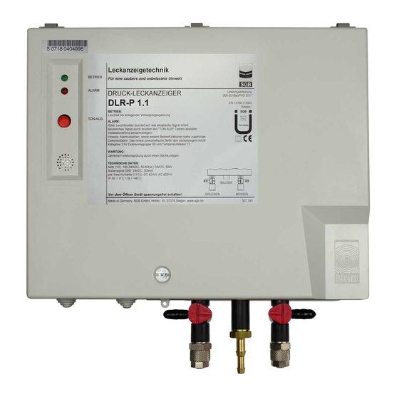
Summary of Contents for SGB DLR-P Series
- Page 1 Documentation Pressure leak detector DLR-P Please read instructions before starting any work Issued: 07/2020 Art. no.: 604422...
-
Page 2: Table Of Contents
Table of Contents Table of Contents General ................4 Information ..............4 Explanation of Symbols ..........4 Limitation of Liability ..........4 Copyright ..............4 Warranty Conditions ..........5 Customer Service ............. 5 Safety ................6 Intended Use ............. 6 Obligation of the Operating Company ....... - Page 3 Table of Contents 11. Disassembly and Disposal ..........39 11.1 Disassembly ............39 11.2 Disposal ..............39 12. Appendix ................ 40 12.1 Dimensions and Drilling Pattern, Plastic Housing with Pulsation Damper ..........40 12.2 Dimensions and Drilling Pattern, Stainless Steel Housing with Pulsation Damper for Installation Outdoors (IP 54), small housing or DLR-P devices with pressure values <...
-
Page 4: General
All information and instructions in this documentation have been compiled considering the applicable norms and regulations, the state of the art and our longstanding experience. SGB does not assume any liability in case of: • Noncompliance with these instructions •... -
Page 5: Warranty Conditions
Customer Service Our customer service is available for any inquiries. For information on contacts, please refer to our website sgb.de or the label of the leak detector. - 5 - PRESSURE LEAK DETECTOR DLR-P .. -
Page 6: Safety
Safety 2. Safety Intended Use • For double-walled pipe/fittings with an interstitial space that is suf- ficiently pressure resistant • The leak detector alarm pressure must be at least 1 bar higher than the maximum feed pressure in the product-transporting pipe. •... -
Page 7: Qualification
Qualification The personnel must be capable of independently recognizing and avoiding potential risks based on their qualifications. Companies commissioning leak detectors should have completed re- spective training with SGB, through SGB or its authorized representa- WARNING! tive. Danger to humans National guidelines must be adhered to. -
Page 8: Fundamental Hazards
Safety • Suitable clothing (risk of electrostatic charge) • Suitable tools (in accordance with EN 1127) • Suitable combustible gas indicator calibrated to the existing vapor- air mixture (work should be performed only at a concentration of 50 % below the lower explosion limit) •... -
Page 9: Technical Data Of The Leak Detector
< 5.5 Special switching values agreed to by SGB and customers The table lists the opening pressure for overpressure protection at which the volume flow of the pump is diverted. The operating pressure (initial opening) is lower. - 9 -... -
Page 10: Field Of Application
Technical Data Max. feed pressure in inner pipe Switching value "Alarm ON"; the alarm will be triggered at this pressure level at the latest Switching value “Pump OFF” (= operating pressure) Opening pressure for overpressure valve 1 (interstitial space) ÜDV1 The use of overpressure valves can be omitted if the test pressure of the interstitial space is ... - Page 11 Technical Data 3.4.4 Conveyed product o Liquids hazardous to water with a flash point of > 60°C (Germany: > 55 °C according to TRGS 509 and 751) o Liquids hazardous to water with a flash point of ≤ 60 °C (Germany ≤...
-
Page 12: Design And Function
Design and Function 4. Design and Function Design Interior view of plastic housing with: Signal lamp "Alarm", red Signal lamp "Operation", green Overpressure pump Check valve Buzzer Overpressure valve (interstitial space) “Mute” button Display board Main board Pressure sensor Contact for serial data transfer - 12 - PRESSURE LEAK DETECTOR DLR-P .. - Page 13 Design and Function Interior view of stainless-steel housing, weather-protected, with: Overpressure pump Three-way valve in the pressure line Three-way valve in measuring line Check valve Buzzer Overpressure valve (interstitial space) Display board Main board Pressure sensor Contact for serial data transfer Keypad connection Temperature switch, frost protection - 13 -...
- Page 14 Design and Function Interior view of stainless-steel housing with LOD for DLR-P devices with pressure values < 3.0: Overpressure pump Three-way valve in the pressure line Three-way valve in the measuring line Check valve Buzzer Overpressure valve (interstitial space) Display board Main board Pressure sensor Contact for serial data transfer...
- Page 15 Design and Function Interior view of stainless-steel housing for DLR-P devices with pressure val- ues > 3.0: Overpressure pump Three-way valve in the pressure line Three-way valve in the measuring line Check valve Dust filter Buzzer Overpressure valve (interstitial space) Display board Main board Pressure sensor...
-
Page 16: Normal Operating Condition
Design and Function The pressure leak detector DLR-P monitors both walls of the double- walled system for leaks. The monitoring pressure during operation is higher than any pressure on the inner or outer wall, so that leaks will be indicated by a pressure drop. Air is used as leak detection medium. -
Page 17: Overpressure Valve
With sufficient pressure resistance of the interstitial space, the over- pressure valve can be omitted if so agreed between the manufacturer of the pipe/fitting and SGB. Dry filter A dry filter is needed to dry the incoming ambient air to the point where condensation does not occur in the interstitial space. - Page 18 Design and Function 4.6.2 Function "Turn off audible alarm signal" Shortly press "mute" button once, audible signal turns off, the red LED blinks. Pressing the button again will turn the audible signal on. This function is not available during normal operating conditions and malfunctions.
- Page 19 Design and Function 4.6.5 Acknowledgement of the “Dry filter notification” (only if filter check FC provided) Briefly press the button “Acknowledge dry filter alarm” to shut off the audible signal. The visual signal (alternate flashing of the red and yel- low LEDs) continues.
-
Page 20: Installing The System
Installation 5. Installing the System Basic Instructions o Prior to commencing work, the documentation must be read and un- derstood. In case of ambiguities, please refer to the manufacturer. o The safety instructions in this documentation must be adhered to. o Only qualified service companies may be used for installation o Comply with relevant regulations for prevention of accidents. -
Page 21: Pneumatic Connection Lines, Requirements
Installation (2) Fastening with the provided installation material. TF 180: Vertical with suction opening pointing down TF 200, 300, 400, 600, 1200: Vertical with suction opening point- ing up, beneath the leak detector if possible (3) Connect the dry filter and the aspiration port of the leak detector through a PVC hose (or comparable). -
Page 22: Electrical Cables
Installation 5.5.2.1 Flanged screw connections (for flanged pipes) (1) Lubricate O-rings (2) Insert spacer ring loosely into the screw socket (3) Slide union nut and pressure ring over the pipe (4) Hand-tighten union nut (5) Tighten union nut until need for increased force is clearly notice- able (6) Final assembly: Tighten by another ¼... - Page 23 Installation (3) Regulations of power supply companies must be adhered to (4) Terminal layout (See also section 5.8.5 Block diagram): Power connection (100…240 VAC) Caution: both terminals exist in duplicate! Occupied (with internal pump) External signal (24 VDC in case of alarm, can be turned off by activating the “mute”...
-
Page 24: Installation Examples
Installation Installation Examples 5.8.1 Leak detector DLR-P .. with pulsation damper, pipelines connected in parallel Shut-off valve Overpressure pump Three-way valve in the pressure line Three-way valve in measuring line Housing Overpressure valve Dry filter Connection line Switchboard Double-walled pipe Pressure sensor Pulsation damper - 24 -... - Page 25 Installation 5.8.2 Leak detector DLR-P .. with pulsation damper, pipelines connected in parallel and in series Signal lamp "Alarm", red Shut-off valve Signal lamp "Operation", green Three-way valve in the pressure line Three-way valve in measuring line Test valve Buzzer “Mute”...
- Page 26 Installation 5.8.3 Leak detector DLR-P.., pressure and measuring line installed separated in a ring line Signal lamp "Alarm", red Shut-off valve Signal lamp "Operation", green Three-way valve in the pressure line Three-way valve in measuring line Test valve Buzzer Button “Audible alarm signal”’ Dry filter Double-walled pipe - 26 -...
- Page 27 Installation 5.8.4 Leak detector DLR-P.., instead of pulsation damper, pressure and measuring line connect- ed separately to the interstitial space Signal lamp "Alarm", red Shut-off valve Signal lamp "Operation", green Three-way valve in the pressure line Three-way valve in measuring line Test valve Buzzer “Mute”...
- Page 28 Installation 5.8.5 Block diagram Plastic housing Signal lamp "Alarm", red Pressure sensor Signal lamp "Operation", green Display Overpressure pump Control unit 24.1 Fuse "Power supply", 2 A Power supply unit 24 VDC 24.2 Fuse "Solenoid valve", 1.5 A Contacts for serial data transfer 24.3 Fuse "External signal", 1 A Keypad terminal strip...
- Page 29 Installation Stainless steel housing 24.3 24.1 24.2 100-240V 24VDC 76.2 76.1 Signal lamp "Alarm", red Heating resistor Signal lamp "Operation", green Pressure sensor Overpressure pump Display 24.1 Fuse "Power supply", 2 A Power supply unit 24 VDC Button “Acknowlegement dry filter signal” 24.2 Fuse "Solenoid valve", 1.5 A 24.3...
-
Page 30: Commissioning
Commissioning 6. Commissioning (1) Only perform commissioning once the steps in section 5 "Mount- ing" have been fulfilled. (2) If a leak detector is commissioned on a pipe (fitting) that is al- ready in operation, special protective measures must be taken (e.g. - Page 31 Commissioning (8) After the operating pressure of the leak detector has been reached (pump in leak detector shuts off), turn three-way valve 20 180°, switch off the pump and remove it. (9) Turn three-way valve 21 180° and remove the measuring gauge. (10) Perform a functional check according to section 7.3.
-
Page 32: Functional Check And Maintenance
Functional Check and Maintenance 7. Functional Check and Maintenance General (1) If the leak detection system has been properly installed and is free of leaks, trouble-free operation can be assumed. (2) Frequent switching on or continuous running of the pump indi- cates leaks, which should be corrected within a reasonable time. - Page 33 Functional Check and Maintenance 7.3.1 Test scope Two persons may be required to perform a functional check, depend- ing on the type of pipeline and how it is laid. (1) Coordinate the work to be performed with those responsible for operation on site.
- Page 34 Functional Check and Maintenance 7.3.3 Testing the switching values (1) Attach measuring gauge to connection on three-way valve 21 and turn valve 180°. (2) For pipelines in accordance with 5.8.1 and 5.8.2: Close the shut-off valves on the manifold except for the interstitial space on which the test is being performed.
- Page 35 (1) The system tightness requirement is defined in section 6.1. Determine the test time for each interstitial space (and/or the en- tire monitored system) connected (calculate or use test reports prepared by SGB GmbH). (2) Attach measuring gauge to connection on three-way valve 21 and turn valve 180°.
-
Page 36: Alarm (Malfunction)
Alarm (Malfunction) 8. Alarm (Malfunction) Alarm (1) The red indicator light lights up, the audible signal sounds. (2) Turn the audible signal off. Malfunction (1) In case of a malfunction, only the red signal lamp will light up (yellow is off), and at the same time the audible signal cannot be acknowledged. -
Page 37: Spare Parts
Spare Parts 9. Spare Parts Spare parts can be found on our shop site shop.sgb.de, e.g. Boards 331670-02 Board VD SMD L with 522380 for DLR-P units (for version in plastic housing) 331661 VD SMD Board without LED, without transformer without TFÜ, installed in housing... -
Page 38: Accessories
Accessories 10. Accessories For accessories, please refer to our website shop.sgb.de e.g. - Installation kits - Electrical isolators - Manifolds - Remote data transmission (LOD) - Pressure limiter - Dry filter/funnel for refilling - P version, housing with IP 54 - 38 - PRESSURE LEAK DETECTOR DLR-P .. -
Page 39: Disassembly And Disposal
Disassembly and Disposal 11. Disassembly and Disposal 11.1 Disassembly Prior to and during works, make sure the unit is free of gas and the breathing air contains sufficient oxygen levels Seal any openings gas-tight through which an explosion atmosphere can carry over. Avoid using spark-producing tools (saws, parting grinders, etc.) for disassembly whenever possible. -
Page 40: Appendix
Appendix 12. Appendix 12.1 Dimensions and Drilling Pattern, Plastic Housing with Pulsation Damper Space needed to remove the housing lid Space needed to open the housing lid Depth = 110 mm - 40 - PRESSURE LEAK DETECTOR DLR-P .. -
Page 41: Dimensions And Drilling Pattern, Stainless Steel
Appendix 12.2 Dimensions and Drilling Pattern, Stainless Steel Housing with Pulsation Damper for Installation Outdoors (IP 54), small housing or DLR-P devices with pressure values < 3.0 Ø8,5 Depth = 80 mm - 41 - PRESSURE LEAK DETECTOR DLR-P .. -
Page 42: Dimensions And Drilling Pattern, Stainless Steel
Appendix 12.3 Dimensions and Drilling Pattern, Stainless Steel Housing with Pulsation Damper for Installation Outdoors (IP 54), big housing or DLR-P devices with pressure values > 3.0 Ø8,5 Depth = 80 mm - 42 - PRESSURE LEAK DETECTOR DLR-P .. -
Page 43: Declaration Of Conformity
Appendix 12.4 Declaration of Conformity SGB GmbH Hofstr. 10 57076 Siegen, Germany, hereby declare in sole responsibility that the leak detectors DLR-P are in conformity with the essential requirements of the EU directives listed below. In case the device is modified or used in a way that has not been agreed with us, this declaration shall lose its validity. -
Page 44: Declaration Of Performance
Pressure leak detector type DLR-P .. Use: Class I pressure leak detector for monitoring double-walled pipe- lines Manufacturer: SGB GmbH, Hofstraße 10, 57076 Siegen, Germany Tel.: +49 271 48964-0, E-mail: sgb@sgb.de Authorized representative: n. A. System for assessment and verification of constancy of performance:... -
Page 45: Certifications Tüv Nord
Appendix 12.7 Certifications TÜV Nord - 45 - PRESSURE LEAK DETECTOR DLR-P .. - Page 46 Appendix - 46 - PRESSURE LEAK DETECTOR DLR-P ..
- Page 47 Notes ________________________________________________________________________________________________ ________________________________________________________________________________________________ ________________________________________________________________________________________________ ________________________________________________________________________________________________ ________________________________________________________________________________________________ ________________________________________________________________________________________________ ________________________________________________________________________________________________ ________________________________________________________________________________________________ ________________________________________________________________________________________________ ________________________________________________________________________________________________ ________________________________________________________________________________________________ ________________________________________________________________________________________________ ________________________________________________________________________________________________ ________________________________________________________________________________________________ ________________________________________________________________________________________________ ________________________________________________________________________________________________ ________________________________________________________________________________________________ ________________________________________________________________________________________________ ________________________________________________________________________________________________ ________________________________________________________________________________________________ ________________________________________________________________________________________________ ________________________________________________________________________________________________ ________________________________________________________________________________________________ ________________________________________________________________________________________________ ________________________________________________________________________________________________ ________________________________________________________________________________________________ ________________________________________________________________________________________________ ________________________________________________________________________________________________ ________________________________________________________________________________________________ ________________________________________________________________________________________________ ________________________________________________________________________________________________ ________________________________________________________________________________________________ - 47 - PRESSURE LEAK DETECTOR DLR-P ..
- Page 48 Hofstr. 10 57076 Siegen Germany T +49 271 48964-0 Photos and dimensions are not binding E sgb@sgb.de for the extent of delivery. Subject to - 48 - PRESSURE LEAK DETECTOR DLR-P .. Text W www.sgb.de changes. © SGB GmbH, 07/2020...
Need help?
Do you have a question about the DLR-P Series and is the answer not in the manual?
Questions and answers