
Related Manuals for SGB DLR-GS


Summary of Contents for SGB DLR-GS
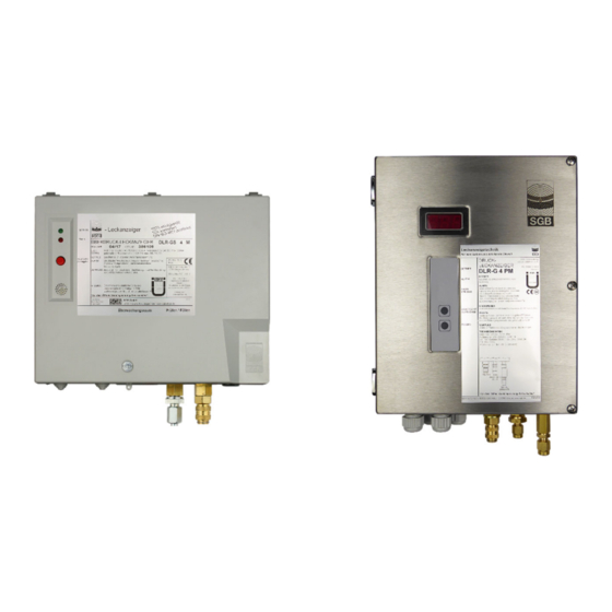
- Page 1 Documentation Pressure Leak Detector DLR-GS Please read instructions prior to commencing any work As of: 08/2020 Item no.: 604302...
- Page 2 DLR pressure leak detectors are available in different versions that are described more precisely by the suffix characters. The levels of availability and the possible combinations depend on the de- vice. Please contact our sales team. Phone +49 271 48964-0, email sgb@sgb.de DLR- … .. P M N LE/LG „Service indication”: integrated service...
-
Page 3: Table Of Contents
6.2 Commissioning the Leak Detector ....... 26 6.3 Changing the Pressure Level ........27 7. Functional Check and Maintenance ........28 7.1 General ................ 28 7.2 Maintenance ..............28 7.3 Functional Check ............28 PRESSURE LEAK DETECTOR DLR-GS .. - 3 - 06/08/2020... - Page 4 Housing for Installation Outdoors (IP 54) ..... 36 12.3 Declaration of Conformity ..........37 12.4 Declaration of Performance ......... 38 12.5 Manufacturer’s declaration of compliance ....38 12.6 Certification TÜV Nord ..........39 - 4 - PRESSURE LEAK DETECTOR DLR-GS .. 06/08/2020...
-
Page 5: General
General Information These instructions provide important notes on using the leak detector DLR-GS. Complying with all safety instructions and guidelines is a prerequisite for safe working. Furthermore, any local regulations for prevention of accidents appli- cable at the site of use of the leak detector and general safety instruc- tions must be complied with. -
Page 6: Warranty Conditions
General Warranty Conditions We provide warranty for the leak detector DLR-GS for a period of 24 months from the day of installation on site in accordance with the General Terms & Conditions. The maximum warranty period is 27 months from our date of sale. -
Page 7: Safety
Section 3.4.5 must be complied with. Any claims arising from misuse are excluded. Obligation of the Operating Company The leak detector DLR-GS is used in a commercial environment. The operating company is therefore subject to statutory occupational safety obligations. -
Page 8: Qualification
Qualification The personnel must be capable of independently recognizing and avoiding potential risks based on their qualifications. Companies commissioning leak detectors should have completed re- spective training with SGB, through SGB or its authorized representa- WARNING! tive. Danger to hu- National guidelines must be adhered to. -
Page 9: Fundamental Hazards
Before entering, the corresponding protective measures must be taken and it must be ensured that no gas and sufficient oxygen are present. Other manufacturers' or countries' regulations may provide different percentages PRESSURE LEAK DETECTOR DLR-GS .. - 9 - 06/08/2020... -
Page 10: Technical Data Of The Leak Detector
DC ≤ 25 W or AC ≤ 50 VA Terminals 17…19 (voltage-free): DC ≤ 25 W or AC ≤ 50 VA Fuse protection: max. 10 A Overvoltage category: With Ethernet board max. 150 mA - 10 - PRESSURE LEAK DETECTOR DLR-GS .. 06/08/2020... -
Page 11: Switching Values
Switching value "Alarm OFF"; the alarm will be deactivated if this value is AOFF exceeded type 1 to 8 approx. 250 mbar type 10 to 16 approx. 500 mbar Switches 1 to 9 for determining the pressure level PRESSURE LEAK DETECTOR DLR-GS .. - 11 - 06/08/2020... -
Page 12: Field Of Application
Liquids hazardous to water, even with a flash point of ≤ 60°C (for Germany ≤ 55°C according to TRGS 509 and TRGS 751). Chapter 3.4.5 is to be observed. The conveyed product may not react with the leak detection me- dium. - 12 - PRESSURE LEAK DETECTOR DLR-GS .. 06/08/2020... - Page 13 3.3 (informative) for EN 13160. If the evaluation of the device categories has different results due to operational regulations or for any other reasons, the use of the leak detector must be checked separately. PRESSURE LEAK DETECTOR DLR-GS .. - 13 - 06/08/2020...
-
Page 14: Design And Function
Interior view of plastic housing with: Signal lamp "Alarm", red Signal lamp "Operation", green Signal lamp "Refilling required", yellow Button "Commissioning" (filling) Buzzer “Mute” Button Display board Main board Pressure sensor Contact for serial data transfer - 14 - PRESSURE LEAK DETECTOR DLR-GS .. 06/08/2020... - Page 15 Interior view of stainless-steel housing, weather-protected, with: Solenoid valve Buzzer 70-1 Overpressure valve (interstitial space) 70-2 Overpressure valve (supply) Display board Main board Pressure sensor Contact for serial data transfer Keypad terminal strip Temperature switch, frost protection PRESSURE LEAK DETECTOR DLR-GS .. - 15 - 06/08/2020...
-
Page 16: Normal Operating Condition
Design and Function The pressure leak detector DLR-GS monitors both walls of the dou- ble-walled system for leaks. The monitoring pressure during operation is higher than any pressure on the inner or outer wall, so that leaks will be indicated by a pressure drop. -
Page 17: Displays And Controls
Press and hold the "Mute" button (about 10 seconds). The alarm will be triggered until the button is released. This inquiry is only possible if the pressure in the system has ex- ceeded the "Alarm OFF" pressure. PRESSURE LEAK DETECTOR DLR-GS .. - 17 - 06/08/2020... -
Page 18: Mounting The System
(4) NOT in potentially explosive areas. (5) Dimensions of housings and drilling patterns are illustrated in Ap- pendix 12.1 and 12.2, respectively. - 18 - PRESSURE LEAK DETECTOR DLR-GS .. 06/08/2020... -
Page 19: Selecting The Pressure Gas Bottle And The Pressure Reducer
(2) Mount the test equipment with pressure reducer at the pres- sure gas bottle. (3) Connect the test equipment to the leak detector. If necessary, install commercial fittings for plastic pipes (specified bending radii). PRESSURE LEAK DETECTOR DLR-GS .. - 19 - 06/08/2020... -
Page 20: Electrical Cables
Electrical Cables Power connection: 2.5 mm without ferrule 1.5 mm with ferrule and plastic collar Voltage-free contacts and external signal: 1.5 mm without ferrule 0.75 mm with ferrule and plastic collar - 20 - PRESSURE LEAK DETECTOR DLR-GS .. 06/08/2020... -
Page 21: Electrical Wiring Diagram
24 V DC as permanent power supply to power other assemblies or, for a device with a supply voltage of 24 V DC, the power supply is connected here For Germany: also VDE regulations PRESSURE LEAK DETECTOR DLR-GS .. - 21 - 06/08/2020... - Page 22 (2) Insert cable into the open terminal. (3) Hold cable and remove screwdriver. (4) Check cable for a tight fit and install more cables to the terminals using the same process. - 22 - PRESSURE LEAK DETECTOR DLR-GS .. 06/08/2020...
-
Page 23: Installation Examples
Mounting Installation Examples 5.9.1 Leak detector DLR-GS .. (single, underground pipeline and/or above-ground riser in the building 06.2 Signal lamp "Alarm", red Test coupling Shut-off cock Test valve Shut-off valve (on pressure reducer) Buzzer 06.2 Coupling, on the leak detector side “Mute”... - Page 24 Mounting 5.9.2 Leak detector DLR-GS .. (underground pipeline, series connection) 06.2 Signal lamp "Alarm", red Test coupling Shut-off cock Test valve Shut-off valve Buzzer 06.2 Coupling, on the leak detector side “Mute” Button Signal lamp "Operation", green Main circuit board...
- Page 25 Button "Filling" Display Solenoid valve Control unit Signal lamp "Refilling", yellow Power supply unit 24 V DC 59.2 Relay "External signal" Contacts for serial data transfer 59.3 Relay "Alarm" Keypad terminal strip PRESSURE LEAK DETECTOR DLR-GS .. - 25 - 06/08/2020...
-
Page 26: Commissioning
(check the settings for the pressure reducer as well, if necessary). For Germany: Additional DIBT requirements must be considered for such double-walled pipes. - 26 - PRESSURE LEAK DETECTOR DLR-GS .. 06/08/2020... -
Page 27: Changing The Pressure Level
(3) If the switch positions 1-9 are changed at the construction site, it must be assured that the operating pressure to be built up does not exceed the test pressure of the interstitial space. PRESSURE LEAK DETECTOR DLR-GS .. - 27 - 06/08/2020... -
Page 28: Functional Check And Maintenance
For Germany: Technical service according to water law with expertise in leak detection systems. For Eu- rope: Authorization by the manufacturer For Germany: In addition, national laws apply (e.g. AwSV) - 28 - PRESSURE LEAK DETECTOR DLR-GS .. 06/08/2020... - Page 29 (2) Insert the test equipment into the coupling 6.2 (3) Insert the manometer into the test coupling 51 of the test equip- ment. PRESSURE LEAK DETECTOR DLR-GS .. - 29 - 06/08/2020...
- Page 30 (if connected to an intersti- tial space). This section assumes that the operating pressure has been built up in the interstitial space and the pres- sure has been compensated. - 30 - PRESSURE LEAK DETECTOR DLR-GS .. 06/08/2020...
-
Page 31: Alarm (Malfunction)
(1) Inform the installation company immediately and state the display from the preceding paragraph. (2) Determine the cause for the alarm, fix it, and then perform a func- tional check for the leak detection system according to section 7.3. PRESSURE LEAK DETECTOR DLR-GS .. - 31 - 06/08/2020... -
Page 32: Spare Parts
Display board for electronic leak indicator, VL, VLR, DL, DLG, DLR-G, DLR-P Manifold: 412690 Manifold DLR-GS with sensor 20 bar and flange plate in- cluding test coupling (please indicate screw connection) 412691 Manifold DLR-GS with sensor 40 bar and flange plate in-... -
Page 33: Accessories
Accessories 10. Accessories For accessories please refer to our online shop shop.sgb.de, e.g. Installation kits Electrical isolators Manifolds Pressure reducers Remote data transmission (LOD) P version, housing with IP 54 PRESSURE LEAK DETECTOR DLR-GS .. - 33 - 06/08/2020... -
Page 34: Disassembly And Disposal
EN 1127 or the area must be free of explosive at- mosphere. Avoid the build-up of electrostatic charges (e.g. through friction). 11.2 Disposal Properly dispose of contaminated components (possibly through out- gassing). Properly dispose of electronic components. - 34 - PRESSURE LEAK DETECTOR DLR-GS .. 06/08/2020... -
Page 35: Appendix
Appendix Appendix 12.1 Dimensions and Drilling Pattern, Plastic Housing Space needed to open the housing lid Space needed to remove the housing lid D = 110 PRESSURE LEAK DETECTOR DLR-GS .. - 35 - 06/08/2020... -
Page 36: Dimensions And Drilling Pattern, Stainless Steel Housing For Installation Outdoors (Ip 54)
Appendix 12.2 Dimensions and Drilling Pattern, Stainless Steel Housing for Installation Outdoors (IP 54) Ø8,5 D = 80 - 36 - PRESSURE LEAK DETECTOR DLR-GS .. 06/08/2020... -
Page 37: Declaration Of Conformity
3 devices. The following documents have been consulted: EN 1127-1: 2011 The ignition hazard assessment did not result in any additional haz- ards. Conformity is declared by: ppa. Martin Hücking (Technical Director) As of: 02/2019 PRESSURE LEAK DETECTOR DLR-GS .. - 37 - 06/08/2020... -
Page 38: Declaration Of Performance
Pressure leak detector type DLR-GS Usage purpose: Class I pressure leak detector for monitoring double-walled pipes Manufacturer: SGB GmbH, Hofstr. 10, 57076 Siegen, Germany Phone: +49 271 48964-0, E-Mail: sgb@sgb.de Authorized representative: System of assessment and verification of constancy of performance: System 3... -
Page 39: Certification Tüv Nord
Appendix 12.6 Certification TÜV Nord PRESSURE LEAK DETECTOR DLR-GS .. - 39 - 06/08/2020... - Page 40 SGB GmbH Hofstr. 10 57076 Siegen Germany +49 271 48964-0 Photos and dimension are not binding sgb@sgb.de for the extent of delivery. Subject to W www.sgb.de changes. © SGB GmbH, 08/2020 - 40 - PRESSURE LEAK DETECTOR DLR-GS .. 06/08/2020...
Need help?
Do you have a question about the DLR-GS and is the answer not in the manual?
Questions and answers