
Subscribe to Our Youtube Channel
Related Manuals for SGB DLR-P CV Series


Summary of Contents for SGB DLR-P CV Series
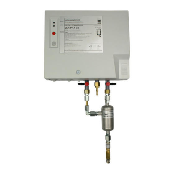
- Page 1 Documentation Pressure leak detector DLR-P .. CV Please read the instructions before commencing any work Last updated: 07/2020 Item no.: 604442...
-
Page 2: Table Of Contents
Contents Contents 1. General ................. 4 1.1 Information ..............4 1.2 Explanation of symbols ..........4 1.3 Limitation of liability ............4 1.4 Copyright ................ 4 1.5 Warranty ................. 5 1.6 Customer Service ............5 2. Safety ..................6 2.1 Intended Use ..............6 2.2 ... - Page 3 Contents 11. Disassembly and disposal ..........35 11.1 Disassembly .............. 35 11.2 Disposal ..............35 12. Appendix ................36 12.1 Dimensions and drilling pattern, plastic housing ..36 12.2 Dimensions and drilling pattern, stainless steel housing for outdoor installation (IP 54) ...... 37 12.4 ...
-
Page 4: General
deployment of unqualified personnel, unauthorized conversions, connection to systems not approved by SGB. Copyright The contents, texts, drawings, pictures, and any other representations are protected by copyright and are subject to industrial property rights. Any misuse is a criminal offence. -
Page 5: Warranty
Our Customer Service department is available to provide you with in- formation. You can find information about contacts on the World Wide Web at sgb.de or on the rating plate of the leak detector. PRESSURE LEAK DETECTOR DLR-P .. CV... -
Page 6: Safety
Safety Safety Intended Use For underground, double-walled plastic pipes The inner pipe is unpressurised (= filling, intake or ventilation pipe) Pressure resistance of the interstitial space at least PN 5 Earthing/equipotential bonding in accordance with applicable regu- lations ... -
Page 7: Qualification
The personnel must be sufficiently qualified to recognize and avoid possible dangers on their own. Companies that put the leak detector into operation should have been trained at SGB, by SGB or by the authorized representative. WARNING! National regulations must be complied with. -
Page 8: Basic Hazards
Safety If work is carried out in areas with a potentially explosive atmosphere, the following items of equipment are required as an absolute mini- mum: Suitable clothing (risk of a build-up of electrostatic charge) Suitable tools (compliant with EN 1127) ... -
Page 9: Technical Data Of The Leak Detector
5.0 < 1.0 > 2.0 < 2.4 Special values agreed between SGB and the customer. Max. delivery pressure in the inner pipe "Alarm ON" switching value – an alarm is triggered at the lat- AL_ON est when this value is reached "Pump OFF“... -
Page 10: Application Area
Technical Data Application area 3.4.1 Requirements for the interstitial space o Verification of the pressure resistance of the interstitial space (see 3.3, switching values, table, column "p " for the minimum test TEST pressure of the interstitial space) o Verification of the suitability of the interstitial space (for Germany: building authority certificate of suitability). - Page 11 Technical Data Based on this approach, additional measures are to be implemented: o Suitable flame barriers (designed to deal with overpressure) at every inlet to the interstitial space. o Check valve in the connection line, to prevent back-flow of poten- tially explosive vapor-air mixtures.
-
Page 12: Design And Function
Design and function Design and function Design Interior view of plastic housing with: Signal lamp – "Alarm" – red Signal lamp – "Operation" – green Overpressure pump Check valve Buzzer “Mute” button Display board Main circuit board Pressure sensor Contact for serial data transfer CV, check valve as isolator - 12 - PRESSURE LEAK DETECTOR DLR-P .. - Page 13 Design and function Interior view of stainless steel, weather-proof housing with pulsation damper, with: Overpressure pump Three-way valve in the pressure line Three-way valve in the measuring line Check valve Dust filter Buzzer Display board Main circuit board Pressure sensor Contact for serial data transfer Keypad connection CV, check valve as isolator...
-
Page 14: Normal Operation
Design and function The pressure leak detector DLR-P..CV monitors both walls of the double-walled system for leaks. The monitoring pressure under nor- mal operating conditions is higher than any other pressure applied to the inner or outer wall, so that leaks are indicated through a drop in pressure. -
Page 15: Dry Filter
Design and function Dry filter A dry filter is needed to dry the drawn-in ambient air enough so that no condensation occurs in the interstitial space. The minimum requirement for underground interstitial spaces is a TF 200; but larger ones can also be used. The dry filter is designed to last for a year provided the equipment is used for its proper intended purpose and no additional temperature fluctuations occur. - Page 16 Design and function 4.5.3 Function: "Test visual and audible alarm signal" Press the "mute" button and keep it pressed (approx. 10 seconds) – the alarm signal is triggered until the button is released again. This test is only possible if the pressure in the system has exceeded the "Alarm OFF"...
-
Page 17: Installation Of The System
Installation Installation of the system General Information o Before starting work, the documentation must be read and under- stood. If anything is unclear, please contact the manufacturer. o The safety instructions in this documentation must be observed. o Installation and assembly must only be performed by qualified companies o The relevant accident prevention regulations must be complied with. -
Page 18: Pneumatic Connection Lines, Requirements
Installation (3) Attachment with mounting materials supplied. TF 180: Vertical with intake opening facing downwards TF 200, 300, 400, 600, 1200: Vertical with intake opening facing upwards, if possible, near the leak detector (4) The dry filter and intake connection port of the leak detector should be connected via a PVC hose (or similar). -
Page 19: Electrical Cables
Installation 5.5.2 Between the leak detector and the interstitial space (1) Select and lay suitable pipe. (2) When laying the hose/pipe, check that the hoses are protected against damage when the manhole is inspected. (3) Observe earthing/potential equalization of metal parts in non- conductive connection lines. -
Page 20: Electrical Connection
Floating contacts and external signal: Suggested cable: Ölflex Truck 1700 1.5 mm without wire end ferrule 0.75 mm with wire end ferrule and plastic collar Electrical connection (1) Power supply in the range of 100 to 240 V (terminals 1/2) or di- rect with 24 V DC at terminals 40/41. - Page 21 Installation 5.7.1 Connection of the wires (1) Press in the orange point using a screwdriver. This opens the tension spring of the terminal. (2) Insert cable into the opened terminal. (3) Hold cable in place and remove screwdriver. (4) Check cable for tightness and connect other cables to the termi- nals in the same way.
-
Page 22: Installation Examples
Installation Installation examples 5.8.1 Leak detector DLR-P .. CV, pipes connected in parallel Stop valve Overpressure pump Three-way valve in the pressure line Three-way valve in the measuring line Housing Test valve Check valve Dry filter Connection line Double-walled pipe Pressure sensor Pulsation damper CV, check valve as isolator... - Page 23 Installation 5.8.2 Leak detector DLR-P .. CV, pipes connected in parallel Signal lamp – "Alarm" – red Signal lamp – "Operation" – green Three-way valve in the pressure line Three-way valve in the measuring line Test valve Check valve Buzzer “Mute”...
- Page 24 Installation 5.8.3 Block diagram, plastic housing Signal lamp – "Alarm" – red Signal lamp – "Operation" – green Overpressure pump 24.1 Fuse – "power supply", 2 A 24.2 Fuse – "solenoid valve", 1.5 A 24.3 Fuse – "external signal", 1 A Signal lamp –...
- Page 25 Installation 5.8.4 Block diagram, VA housing Signal lamp – "Alarm" – red Signal lamp – "Operation" – green Overpressure pump 24.1 Fuse – "power supply", 2 A 24.2 Fuse – "solenoid valve", 1.5 A 24.3 Fuse – "external signal", 1 A Signal lamp –...
-
Page 26: Start-Up
Start-up Start-up (1) Do not perform the start-up until the points from section 5 "Com- missioning" have been fulfilled. (2) If a leak detector is put into operation on a pipe (or fitting) which is already in operation, then special protection measures need to be taken (e.g. - Page 27 Start-up (7) Check all connection points with a foaming agent for leak tight- ness. (8) After reaching the operating pressure of the leak detector (pump in the leak detector switches off), the three-way valve 20 must be rotated by 180° and the pump must be switched off and removed. (9) Rotate three-way valve 21 by 180°...
-
Page 28: Function Test And Maintenance
Function test and maintenance Function test and maintenance General (1) It can be assumed that the system will work correctly without any problems if the leak detection system is installed correctly without leaks. (2) If the pump switches on frequently or runs continuously, this indi- cates that leaks are present that must be rectified within a rea- sonable time. -
Page 29: Function Test
Function test and maintenance Function test Checking of the functional and operational safety and reliability must be performed: o after every start-up o in accordance with the intervals laid out in section 7.2 o whenever a fault has been rectified. 7.3.1 Scope of testing Depending on the type or layout of the pipes, 2 people may be need-... - Page 30 Function test and maintenance (3) Open all test valves at the end away from the leak detector and leave open. (4) Open the shut-off device in the distributor of the interstitial space which is to be tested; the pressure on the measuring gauge will drop.
- Page 31 Determine the testing time for each connected interstitial space (and/or the whole monitored system - calculate it or use the pre- pared SGB GmbH test reports). (2) Connect measuring gauge to the spout of the three-way valve 21 and rotate the valve by 180°.
-
Page 32: Alarm (Fault)
Alarm (fault) Alarm (fault) Alarm (1) The red signal lamp comes on and an acoustic signal sounds. (2) Switch off the acoustic signal. Fault (1) In the case of a fault, only the red signal lamp lights (yellow is off); at the same time, the audible signal cannot be acknowl- edged. -
Page 33: Spare Parts
Spare parts Spare parts Spare parts can be found on our shop site shop.sgb.de, e.g. PCBs: 331670-02 VD SMD L PCB with 522380 for DLR-P devices (For implementation in plastic housing) 331661 VD SMD PCB without LED, without transformer without dry filter monitoring unit, incorporated in housing... -
Page 34: Accessories
Accessories 10. Accessories You can find accessories on our website shop.sgb.de and e.g. - Mounting kits - Electrical separators - Manifolds - Remote data transmission (LOD) - Pressure limiting device - Dry filter/feed hopper - P version, housing with IP 54 - 34 - PRESSURE LEAK DETECTOR DLR-P .. -
Page 35: Disassembly And Disposal
Disassembly and disposal 11. Disassembly and disposal 11.1 Disassembly Check for absence of gas and sufficient oxygen content of the air be- fore and during the work Seal any openings gas-tight which could otherwise allow the spread of an explosive atmosphere. If possible, do not use tools capable of generating sparks (saw, angle grinder, etc.) for disassembly. -
Page 36: Appendix
Appendix 12. Appendix 12.1 Dimensions and drilling pattern, plastic housing Space requirements for removing the housing Space requirements for opening the housing cover Depth = 110 mm Check Valve - 36 - PRESSURE LEAK DETECTOR DLR-P .. CV 30 July 2020... -
Page 37: Dimensions And Drilling Pattern, Stainless Steel Housing For Outdoor Installation (Ip 54)
Appendix 12.2 Dimensions and drilling pattern, stainless steel housing for outdoor installation (IP 54) Check Valve Depth = 80 mm PRESSURE LEAK DETECTOR DLR-P .. CV - 37 - 30 July 2020... - Page 38 Appendix 12.3 Test device 90° 90° Kl. 1,0 - 38 - PRESSURE LEAK DETECTOR DLR-P .. CV 30 July 2020...
-
Page 39: Overview Of The Ex-Zone Arrangement (Z-078 092R)
Appendix 12.4 Overview of the ex-zone arrangement (Z-078 092R) 21 22 Rückschlagventil Check valve Check Valve CV, check valve as CV, Rückschlagventil isolator als Trennelement Zone 2 Zone 1 Zone 0 Flammen- sperre als Detonation flame Zonen- arrester as zone trennung separation Doppelwandiges... -
Page 40: Declaration Of Eu Conformity
Appendix 12.5 Declaration of EU conformity SGB GmbH Hofstraße 10 57076 Siegen, Germany, hereby declare in sole responsibility that the leak detectors DLR-P .. CV comply with the basic requirements of the EU Directives listed below. This declaration shall lose its validity if the device is modified or used for another purpose without our agreement. -
Page 41: Declaration Of Performance
Pressure leak detector type DLR-P .. CV Intended purpose: Class I pressure leak detector for monitoring double-walled pipes Manufacturer: SGB GmbH, Hofstraße 10, 57076 Siegen, Germany Tel.: +49 271 48964-0, e-mail: sgb@sgb.de Authorized person: System for assessment and verification of consistency of performance: System 3... -
Page 42: Certifications Tüv Nord
Appendix 12.8 Certifications TÜV Nord - 42 - PRESSURE LEAK DETECTOR DLR-P .. CV 30 July 2020... - Page 43 Appendix PRESSURE LEAK DETECTOR DLR-P .. CV - 43 - 30 July 2020...
- Page 44 Hofstr. 10 57076 Siegen Germany +49 271 48964-0 Photos and dimensions are not binding sgb@sgb.de for the extent of delivery. Subject to Text www.sgb.de changes. ©SGB GmbH, 07/2020 - 44 - PRESSURE LEAK DETECTOR DLR-P .. CV 30 July 2020...
Need help?
Do you have a question about the DLR-P CV Series and is the answer not in the manual?
Questions and answers