
Related Manuals for SGB DLR-GS Series


Summary of Contents for SGB DLR-GS Series
- Page 1 Overpressure leak detector DLR-GS No.: 604 302 Documentation DLR-GS Issue: 05/2015 SGB GMBH Hofstraße 10 57076 Siegen GERMANY...
- Page 2 Overview – Design Variant OVERPRESSURE LEAK DETECTOR DLR-GS Overview of the design variants The overpressure leak detector DLR-GS is available in various designs, which are described in more detail by the letters that follow. DLR-GS…. PMN “Feed required” (N), the leak detector indicates by means of a diode that the pressure in the interstitial space has decreased...
- Page 3 OVERPRESSURE LEAK DETECTOR DLR-GS .. Documentation contents Technical description of the overpressure leak detector DLR-GS 13 pages Drawings relating to the technical description 4 pages Appendix to the technical description 2 pages Dimensions and drilling template 2 pages Work Sheet AB-820 500 Mounting screwed connections 2 pages EC Declaration of conformity 1 page...
-
Page 4: Table Of Contents
OVERPRESSURE LEAK DETECTOR DLR-GS .. Contents Page Subject Area of use Requirements for interstitial spaces Pipes Fittings Materials carried in the pipes / leak detection medium Description of functions and operation Switching values and pressure values Normal operation Functions in the event of a leak Pressure relief valve Description of the display and control elements Installation and assembly instructions... -
Page 5: Subject
OVERPRESSURE LEAK DETECTOR DLR-GS .. 1. Subject Overpressure leak detector without built-in pressure generator for double-walled pipes and fittings, with inert gas or air used as the leak detection medium. DLR-GS .. (the dots are replaced by the respective alarm pressure in bar) 2. -
Page 6: Description Of Functions And Operation
OVERPRESSURE LEAK DETECTOR DLR-GS .. The resistance of the pipeline/fittings to the material being conveyed must be verified by third parties (e.g. operator, manufacturer of the pipeline/fittings ..) 3. Description of functions and operation The overpressure leak detector DLR-GS monitors both walls of the double-walled system for leaks. -
Page 7: Pressure Relief Valve
OVERPRESSURE LEAK DETECTOR DLR-GS .. Optionally, an additional relay can be used for potential-free contacting when the pressure falls below the "Feed required" point. The pressure value for "Feed required" is about 1 bar above the switching value "Alarm ON". 3.4. -
Page 8: Installation And Assembly Instructions
OVERPRESSURE LEAK DETECTOR DLR-GS .. 4. Installation and assembly instructions 4.1. General notes (1) Installation and assembly must only be performed by qualified firms (2) The relevant accident prevention regulations must be complied with. (3) Explosion protection requirements must be satisfied (where necessary), such as laws on the basis of the European Directive 1999/92/EG and/or other applicable codes. -
Page 9: Installation Of The Connecting Lines (Leak Detector -> Interstitial Space)
(See Appendix B.) (3) The maximum pressure which can be set on the pressure reducer must not be greater than the test pressure of the interstitial space (SGB recommendation). 4.6. Gas canister and pressure reducer (functional tests and commissioning) (1) After setting up the gas canister securely, remove the protection cap. -
Page 10: Electrical Connections
OVERPRESSURE LEAK DETECTOR DLR-GS .. (8) After functional testing has been carried out – Close shut-off valve on the pressure reducer – Close the canister shut-off valve. – Remove the pressure reducer from the canister (attention: gas escapes until the pressure reducer is depressurised). -
Page 11: Changing The Pressure Level
OVERPRESSURE LEAK DETECTOR DLR-GS .. (4) Once the pneumatic connections have been made, connect the electrical supply. (5) Check that the signal lamps for "Operation" and "Alarm" light up and that the acoustic alarm signal sounds; if necessary switch off the acoustic alarm. (6) Pressure build-up via device shown in drawing P-115 520 Note:If pressure does not build up even though the gas canister is connected, then the leak must be located and rectified (you may need to check that the setting on the pressure reducer is correct). -
Page 12: Maintenance
OVERPRESSURE LEAK DETECTOR DLR-GS .. 6.2. Maintenance (1) Maintenance work and functional tests must only be performed by qualified persons (2) Once a year to ensure functional and operational reliability and safety. (3) Scope of testing: as described in section 6.4. (4) Also to be verified: that the conditions in sections 4 and 5 are satisfied. - Page 13 OVERPRESSURE LEAK DETECTOR DLR-GS .. (6) Leak test (section 6.4.4) (7) Set up the equipment ready for operation (section 6.4.5) (8) Completion of a test report by the qualified person, with confirmation of functional and operational safety and reliability. 6.4.2 Continuity test of the interstitial space If several interstitial spaces are connected in parallel, each interstitial space must be tested individually for continuity.
- Page 14 OVERPRESSURE LEAK DETECTOR DLR-GS .. (8) Open stop cock 2.2. (9) Pressure build-up until pressure setpoint; during filling, monitor the pressure on the pressure reducer (test pressure must not be exceeded) and re-adjust if necessary. (10) Close stop cock 2.2 once the pressure setpoint is reached. (11) Repeat steps (7) to (9) several times if necessary until the possible pressure equalizing processes are completed.
-
Page 15: Alarm / Fault
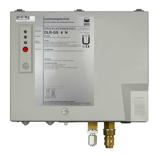
OVERPRESSURE LEAK DETECTOR DLR-GS .. 6.5. Alarm / fault (1) In the event of an alarm, the red signal lamp lights up and the acoustic signal sounds (2) Switch off the acoustic signal. (3) Contact the installation company immediately. (4) Determine and rectify the cause for the alarm, then perform a functional test of the leak detection system as described in section 6.4. - Page 16 OVERPRESSURE LEAK DETECTOR DLR-GS .. Connection, on leak detector side Shut-off valve (on pressure reducer) Signal lamp – "Operation" – green Pressure reducer Pressure accumulator 24.1 Microfuse "External signal" slow-blow 1A 24.2 Microfuse "Transformer" slow-blow 32mA Canister shut-off valve Housing Signal lamp "Feed required"...
- Page 17 06.2 13-04-2007 M1 - 075 000...
- Page 18 06.2 13-04-2007 M2 - 075 000...
-
Page 21: B Switching Values And Pressure Values B
< 15 > 16 > 26 Special values agreed between SGB and the customer. The following abbreviations are used in the table: Maximum operating pressure in the inner pipe (delivery pressure + velocity pressure + pressure due to differences in geodetic height "Alarm ON"... - Page 22 APPENDIX TD OVERPRESSURE LEAK DETECTOR DLR-GS .. Technical data Electrical data Rated input (without external signal) 230 V – 50 Hz – 10 W Contact rating, alarm loop terminals 230 V – 50 Hz – 1 A Contact rating, potential-free contacts max.: 230 V –...
- Page 23 To remove the cover To open the cover B x H x T = 266 x 217 x 110 18-11-2003 Dimension / Drilling...
- Page 24 T = 140 28-06-2005 Drilling / Dimensions...
- Page 25 Work Sheet: AB-820 500 Pneumatic connections 1 Flare type fitting for flare type pipes 1. Lubricate the O-rings 2. Place the intermediate ring loosely in the threaded connection piece 3. Push the union nut and the thrust collar over the pipe 4.
- Page 26 Work Sheet: AB-820 500 Pneumatic connections 5 Tube connections (socket 4 and 6 mm for EXCESS PRESSURE) 1. Push wire or screw clip over the tube 2. Push the tube onto the Cu pipe or the tube socket (if necessary heat or dampen PVC tube), tube must fit tightly all the way round 3.
- Page 27 EC DECLARATION OF CONFORMITY SGB GmbH Hofstraße 10 57076 Siegen, Germany, hereby declare in sole responsibility that the leak detectors DLR-GS .. comply with the essential requirements of the EC directives listed below. This declaration shall lose its validity if the device is modified without consulting us.
- Page 28 A p p r o v a l C e r t i f i c a t e for the design of a leak detector as part of a leak indication device Client: Sicherungsgerätebau GmbH Hofstraße 10 57076 Siegen Dipl.-Ing.
- Page 29 Order no. 0111 BM 21610 Subject Overpressure leak detector as part of a leak detection system for connection to interstitial spaces of double walled pipes. Manufacturer SGB Sicherungsgerätebau GmbH Hof Strasse 10 57076 Siegen Information about the leak detector Type DLR-..
- Page 30 Page 3 of 7 of the Approval Certificate dated February 1, 2006 Order no. 0111 BM 21610 Mode M - The necessary operating overpressure in the interstitial space is provided by connecting a mobile pressure accumulator before starting up the leak detector. The operating modes S and M should be selected via a micro selector switch located in the unit before the leak detector is started up.
- Page 31 Page 4 of 7 of the Approval Certificate dated February 1, 2006 Order no. 0111 BM 21610 Test basis Approval principles for leak detection systems for pipes (ZG-LAGR), Building and testing principles for leak detection devices for pipes (TRbF 502), Leak detection systems EN 13160.
- Page 32 Page 5 of 7 of the Approval Certificate dated February 1, 2006 Order no. 0111 BM 21610 and remains operational. The components of the electronic circuitry integrated in the device remain operational even under the temperature loads. The outcome of mechanical function tests and software tests was positive. Undefined measured values, faulty calibration and failure of the system clock pulse all cause an alarm to be triggered.
- Page 33 Page 6 of 7 of the Approval Certificate dated February 1, 2006 Order no. 0111 BM 21610 Assessment The leak detector of type DLR-... has been approved as suitable as part of a leak indication device operating on the basis of overpressure, and it complies with the requirements of EN 13160 and the approval principles for leak detection devices for pipes and TRbF 502, provided the following conditions are met: The leak detector variants, comprising the signal part and a pressure measuring...
- Page 34 Page 7 of 7 of the Approval Certificate dated February 1, 2006 Order no. 0111 BM 21610 Year of manufacture, Production no., Approval cert. no., Type designation, Rated operating data. Every leak detector is to be subjected to a routine check prior to delivery. In terms of production monitoring, the requirements in EN 13160-1, Annex C, of TRbF 502 and/or ZG-LAGR no.
- Page 35 The switching values are adjusted via a micro switch inside the device. For the operation and installation of the leak detector DLRGS, the technical description of SGB Gerätesicherungsbau GmbH from 25.04.2007 must be observed.
- Page 36 Our warranty shall not apply in the event of faulty or improper installation or improper operation, or if modifications or repairs are carried out without the manufacturer's consent. In case of malfunction, please contact your local specialist company: Stamp of the specialist company Yours sincerely SGB GmbH Hofstr. 10 57076 Siegen, Germany Phone +49 271 48964-0...
Need help?
Do you have a question about the DLR-GS Series and is the answer not in the manual?
Questions and answers