
Subscribe to Our Youtube Channel
Related Manuals for SGB VLR Series


Summary of Contents for SGB VLR Series
- Page 1 Documentation Vacuum leak detector VLR in 100–240 V AC and 24 V DC Read instructions prior to commencing any work As of: 05/2020 Item no.: 605 342...
- Page 2 The levels of availability and the possible combinations depend on the device. Please contact our sales team. Phone +49 0271 48964-0, email sgb@sgb.de VL(R) .. E FA P M MV LG LE S Si T “Tightness alarm”...
-
Page 3: Table Of Contents
Contents Table of Contents 1. Gener ................... 5 1.1 Information ................5 1.2 Explanation of Symbols ............5 1.3 Limitation of Liability ..............5 1.4 Copyright ................. 5 1.5 Warranty Conditions ..............6 1.6 Customer Service ..............6 2. Safety ................... 7 2.1 ... - Page 4 Contents 9. Spare Parts ................40 10. Accessories................40 11. Appendix ................. 41 11.1 Dimension and drilling illustration .......... 41 11.2 Declaration of Conformity ............43 11.3 Declaration of Performance (DoP) ......... 44 11.4 Declaration of Compliance of the Manufacturer (ÜHP) ..44 - 4 - VACUUM LEAK DETECTOR VLR ..
-
Page 5: Gener
All information and instructions in this documentation have been compiled considering the applicable standards and regulations, the state of the art, and our longstanding experience. SGB does not assume any liability in the case of: Noncompliance with these instructions ... -
Page 6: Warranty Conditions
Customer Service Our customer service is available for any inquiries. For information on contacts, please refer to our website www.sgb.de or the label of the leak detector. - 6 - VACUUM LEAK DETECTOR VLR .. and VLR .. MV... -
Page 7: Safety
Qualification The personnel must be capable of independently recognizing and avoiding potential risks based on their qualifications. Companies commissioning leak detectors should have completed relevant training with SGB, through SGB, or through its authorized WARNING! representative. Danger to hu- National guidelines must be adhered to. -
Page 8: Personal Protective Equipment
Safety Personal Protective Equipment Personal protective equipment must be worn during work. o Wear the necessary protective equipment for the work in question o Note and comply with existing PPE signs Entry in the “Safety Book” Wear HV vest Wear safety footwear Wear hard hat Wear gloves –... - Page 9 Safety DANGER From working in chambers The leak detectors are mounted outside the access chambers. Pneumatic connection is usually performed inside the access cham- ber. Therefore, the chamber must be entered in order to complete the mounting process. Before entering, the corresponding protective measures must be tak- en and it must be ensured that no gas and sufficient oxygen are pre- sent.
-
Page 10: Technical Data Of The Leak Detector
- 850 mbar - 570 mbar - 700 mbar - 900 mbar Special values can be agreed upon between the client and SGB. Overpressure alarm (VLR .. with solenoid valve) at +50 mbar * IS = interstitial space - 10 - VACUUM LEAK DETECTOR VLR .. -
Page 11: Field Of Application
Technical Data Field of Application 3.4.1 Pipelines/tubes In factory or on-site construction o Suction lines: The alarm vacuum shall be at least 30 mbar higher than the max underpressure in the inner pipe at the high point of the interstitial space o Pressure lines with feed pressures of up to 5 bar: Version VLR 330 to VLR 570 o Pressure lines with feed pressures of up to 25 bar:... - Page 12 Technical Data 3.4.2 Monitorable fluids Liquids hazardous to water with a flash point of over 60°C (for Ger- many: 55°C in accordance with TRBS and TRGS), e.g., heating oil, diesel, acids, and alkalis. The following also applies: o The materials used must be resistant to the liquids being moni- tored.
-
Page 13: Design And Function
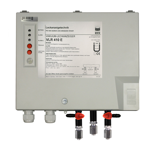
Design and Function Design and Function Design 4.1.1 Plastic housing interior view 01.2 Interior view with: “Alarm” indicator light, red 01.2 “Alarm 2” indicator light, yellow “Operation” indicator light, green Three-way valve in the suction line Three-way valve in the measuring line “Commissioning”... - Page 14 Design and Function 4.1.2 Stainless steel housing internal view Interior view with: Three-way valve in the suction line Three-way valve in the measuring line Vacuum pump Check valve with filter Buzzer Display board Main board Pressure sensor Keypad Contact for serial data transfer Keypad terminal strip Temperature switch, frost protection - 14 -...
-
Page 15: Normal Operating Conditions
Design and Function Normal Operating Conditions The vacuum leak detector is connected to the interstitial space via suction, measuring, and connection line(s). The vacuum generated by the pump is measured and controlled by a pressure sensor. When the operating vacuum is reached (Pump OFF), the pump shuts off. -
Page 16: Displays And Controls
Design and Function The pressure increase is indicated visually and acoustically (pressure build-up alarm). For the version up to 90 bar (additional pressure switch and solenoid valve), the additional pressure switch is actuated in the case of a fast pressure increase, which immediately closes the solenoid valve to protect the leak detector from inadmissably high pressures. - Page 17 Design and Function 4.6.3 “Testing the optical and audible alarm signal” function Press and hold the “Sound off” key (for about 10 seconds). The alarm will be triggered until the key is released. This inquiry is only possible if the pressure in the system has exceed- ed the “Alarm OFF”...
-
Page 18: Mounting The System
Mounting Mounting the System Basic Instructions o Prior to commencing work, the documentation must be read and understood. In case of ambiguities, please ask the manufacturer. o Observe the approvals of the manufacturer for the pipeline and the interstitial space. o The safety instructions in this documentation must be adhered to. -
Page 19: Pneumatic Connection Lines
Mounting Pneumatic Connection Lines 5.3.1 Requirements o At least 6 mm inside clearance o Resistant to the stored or conveyed product o Pressure and vacuum-resistant across the entire temperature range o The full cross section must be maintained (not bent) o Color coding: Measuring line: RED;... -
Page 20: Completing Pneumatic Connections
Mounting o For applications with pressure compensation vessel (see 5.7.4 and 5.7.5): Length of the measuring line from the pressure compensation ves- sel (V=0.1 l) Type 330: 16 m Type 410 12 m Type 500 10 m Type 570 CAUTION: The bottom edge of the pressure compensation vessel must not be lower than the node point;... -
Page 21: Electrical Cables
Mounting 5.4.2 Between leak detector and interstitial space (1) Select and install suitable pipe (2) During installation of the pipe, ensure that it is protected against damage when the manhole chamber is entered (3) Complete the relevant connection (according to the illustrations in the following images) 5.4.2.1 Flanged screw connection (for flanged pipes) (1) Lubricate O-rings... -
Page 22: Electrical Wiring Diagram
Mounting Electrical Wiring Diagram (1) Fixed wiring, i.e., no plug or switch connections. (2) Observe the requirements for electric installations, if necessary, also those of the electric companies. (3) Terminal layout: (see also SL 854 851) Power connection (100–240 V AC) Occupied (vacuum pump) External signal 24 V DC, can be disconnected Solenoid valve... - Page 23 Mounting 5.6.1 Connecting the wires (1) Press down the orange point with a screwdriver. This opens the tension spring of the terminal (2) Insert the cable into the open terminal. (3) Hold the cable and remove the screwdriver. (4) Check the cable for a tight fit and connect more cables to the terminals using the same process.
- Page 24 Mounting 5.6.3 Block diagram (SL 854 851) 100 - 240 V AC 50 Hz L 24 V DC 24 VDC Solenoid valve Pump (24 V DC) Main board Temperature switch Heating Leak detection probe Pressure sensor Display Switching power supply Keypad Solenoid valve monitoring board (MVÜ...
- Page 25 Mounting Installation Examples 5.7.1 Double-walled pipe, connected in parallel, with solenoid valve in the suction line. To be used for feed pressures < 5 bar in the inner pipe. Version VLR .. Shut-off valve Test valve Three-way valve, suction line Suction line Three-way valve, measuring line Connection line...
- Page 26 Mounting 5.7.2 Double-walled pipe, connected in parallel, with solenoid valve in the connection line. To be used for feed pressures 5 bar > p < 25 bar in the inner pipe. Version VLR .. MV 02 Shut-off valve 44 Solenoid valve 20 Three-way valve, suction line 57 Test valve 21 Three-way valve, measuring line...
- Page 27 Mounting 5.7.3 Double-walled pipe with solenoid valve in the connection line and additional pressure switch. To be used for feed pressures 25 bar > p < 90 bar in the inner pipe. Shut-off valve Suction line Three-way valve, suction line Connection line Three-way valve, measuring line Double-walled pipe...
- Page 28 Mounting 5.7.4 Double-walled pipe, connected in parallel (node point in the manifold) Shut-off valve Three-way valve, suction line Three-way valve, measuring line Liquid stop valve Liquid stop valve, connected against the flow direction Measuring line Test valve Suction line Connection line Double-walled pipe Pressure compensation vessel Node point...
- Page 29 Mounting 5.7.5 Double-walled pipe, connected in series ÜR 1 ÜR 2 Shut-off valve Three-way valve, suction line Three-way valve, measuring line Liquid stop valve Measuring line Suction line Nozzle for assembly pump Double-walled pipe VACUUM LEAK DETECTOR VLR .. and VLR .. MV - 29 - 20/05/2020...
- Page 30 Mounting 5.7.6 Double-walled pipe, individual pipe with low vacuum VLR 34 Three-way valve, suction line Three-way valve, measuring line Liquid stop valve Measuring line Test valve Suction line Connection line Double-walled pipe Pressure compensation vessel Node point Here: must (geodetically) be under 157! Lowest point of the interstitial space - 30 - VACUUM LEAK DETECTOR VLR ..
-
Page 31: Commissioning
Commissioning Commissioning (1) Only perform commissioning once the steps in Section 5 “Mount- ing” have been completed. (2) If a leak detector is operated on an interstitial space that is al- ready in operation, special protective measures must be taken (for example, checking that there is no liquid in the interstitial space). - Page 32 Commissioning Turn the valve 180° and switch on the assembly pump. (7) After the operating vacuum of the leak detector has been reached (pump in leak detector shuts off), turn three-way valve 20 180°, switch off the assembly pump, and remove it. (8) Turn three-way valve 21 180°...
-
Page 33: Functional Check And Maintenance
Functional Check and Maintenance Functional Check and Maintenance General (1) If the leak detection system has been properly installed and is free of leaks, trouble-free operation can be assumed. (2) Frequent switching on or continuous running of the pump indi- cates leaks, which should be corrected within a reasonable peri- od of time. - Page 34 Check the probe (if used) (7.3.9) o Create the operating condition (7.3.10) o A test report must be completed, confirming functional and opera- tional safety. Test reports are available for download from the SGB website 7.3.1 Checking free passage of air in the interstitial space...
- Page 35 Functional Check and Maintenance 7.3.2 Testing the switching values with the interstitial space (1) Attach the measuring gauge to the connection on three-way valve 21 and turn the valve 180°. (2) Open the test valve at the end opposite the leak detector; if there are multiple pipe interstitial spaces, the leak detector-side shut- off cocks of the interstitial spaces not included in the test can be closed.
- Page 36 Determine the test period for each interstitial space connected (and/or the entire monitored system) (calculate or use test re- ports prepared by SGB GmbH). (2) Attach the measuring gauge to the connection on three-way valve 21 and turn the valve 180°.
- Page 37 Functional Check and Maintenance on), and if the pressure continues to increase, the excess pres- sure alarm is triggered (yellow LED flashes). (4) With the excess pressure alarm, the pump is switched off and the solenoid valve closes. (5) Relieve excess pressure by detaching the excess pressure test- ing device.
- Page 38 Functional Check and Maintenance (2) Check that the three-way valves are in the correct position. (3) Seal the housing. (4) Seal the shut-off cocks (between the leak detector and interstitial space) for each connected interstitial space in the open position. (5) Attach a sign with troubleshooting information.
-
Page 39: Malfunction (Alarm)
Malfunction (Alarm) Malfunction (Alarm) Alarm Description If an alarm goes off, one must assume that there are vapors stored in the interstitial space of the stored/conveyed product. Take appropri- ate protective measures. (1) An alarm (vacuum loss) is indicated by the red “Alarm” signal lamp lighting up and the sounding of the audible signal, if availa- ble. -
Page 40: Spare Parts
Spare Parts/Accessories Spare Parts See: shop.sgb.de 10. Accessories You can find accessories on our website shop.sgb.de, for example: - Assembly kits - Electrical isolators - Manifolds with suction/measuring connections, expansion mani- folds (e.g., art. no. 195420, 195434) - Testing device/measuring equipment (e.g., art. no. 115392, 115360) - Pressure booster (e.g., art. -
Page 41: 11. Appendix
Appendix 11. Appendix 11.1 Dimension and drilling illustration 11.1.1 Plastic housing -- -- Depth = 110 VACUUM LEAK DETECTOR VLR .. and VLR .. MV - 41 - 20/05/2020... - Page 42 Appendix 11.1.2 Stainless steel housing Ø8,5 Depth = 80 mm - 42 - VACUUM LEAK DETECTOR VLR .. and VLR .. MV 20/05/2020...
-
Page 43: 11.2 Declaration Of Conformity
Appendix 11.2 Declaration of Conformity We, SGB GmbH Hofstrasse 10 57076 Siegen, Germany, hereby declare in sole responsibility that the leak detectors VLR .. and VLR .. MV are in conformity with the essential requirements of the EU directives listed below. -
Page 44: Declaration Of Performance (Dop)
Vacuum leak detector type VLR .. Use: Vacuum leak detector of class I for monitoring double-walled pipes Manufacturer: SGB GmbH, Hofstrasse 10, 57076 Siegen, Germany Phone: +49 271 48964-0; e-mail: sgb@sgb.de Authorized representative: System for assessment and verification of constancy of performance: System 3... - Page 45 Appendix 11.5 TÜV Nord Certification VACUUM LEAK DETECTOR VLR .. and VLR .. MV - 45 - 20/05/2020...
- Page 46 Notes ______________________________________________________________________________ ______________________________________________________________________________ ______________________________________________________________________________ ______________________________________________________________________________ ______________________________________________________________________________ ______________________________________________________________________________ ______________________________________________________________________________ ______________________________________________________________________________ ______________________________________________________________________________ ______________________________________________________________________________ ______________________________________________________________________________ ______________________________________________________________________________ ______________________________________________________________________________ ______________________________________________________________________________ ______________________________________________________________________________ ______________________________________________________________________________ ______________________________________________________________________________ ______________________________________________________________________________ ______________________________________________________________________________ ______________________________________________________________________________ ______________________________________________________________________________ ______________________________________________________________________________ ______________________________________________________________________________ ______________________________________________________________________________ - 46 - VACUUM LEAK DETECTOR VLR .. and VLR .. MV 20/05/2020...
- Page 47 Notes ______________________________________________________________________________ ______________________________________________________________________________ ______________________________________________________________________________ ______________________________________________________________________________ ______________________________________________________________________________ ______________________________________________________________________________ ______________________________________________________________________________ ______________________________________________________________________________ ______________________________________________________________________________ ______________________________________________________________________________ ______________________________________________________________________________ ______________________________________________________________________________ ______________________________________________________________________________ ______________________________________________________________________________ ______________________________________________________________________________ ______________________________________________________________________________ ______________________________________________________________________________ ______________________________________________________________________________ ______________________________________________________________________________ ______________________________________________________________________________ ______________________________________________________________________________ ______________________________________________________________________________ ______________________________________________________________________________ ______________________________________________________________________________ VACUUM LEAK DETECTOR VLR .. and VLR .. MV - 47 - 20/05/2020...
- Page 48 57076 Siegen Germany +49 271 48964-0 Photos and sketches are not binding for the scope of delivery. - 48 - VACUUM LEAK DETECTOR VLR .. and VLR .. MV 20/05/2020 sgb@sgb.de Subject to change without notice. www.sgb.de © SGB GmbH, 05/2020...
Need help?
Do you have a question about the VLR Series and is the answer not in the manual?
Questions and answers