Table of Contents

Related Manuals for SGB VLX-S 350 M


Summary of Contents for SGB VLX-S 350 M
- Page 1 Documentation Vacuum leak detector VLX-S 350 M For 1 up to 6 tanks with a suction line for the leak detector to the lowest point of the interstitial space Read the instructions before starting any work Issued: 08/2020 Art. no.: 602702...
-
Page 2: Table Of Contents
6.2. Commissioning of the leak detector ......29 6.3. Build-up of negative pressure up to operating pressure ............... 30 6.4. Optional data transfer (only available for devices with one display/control panel) ........30 VACUUM LEAK DETECTOR VLX-S 350 M 03/08/2020 - 2 -... - Page 3 5 up to 6 displays) ............36 12.3. EU Declaration of conformity ........37 12.4 Declaration of performance (DoP) ....... 38 12.5. Manufacturer’s declaration of conformity ..... 38 12.6. Certification (TÜV Nord) ..........39 VACUUM LEAK DETECTOR VLX-S 350 M 03/08/2020 - 3 -...
-
Page 4: General
These instructions provide important information on how to handle the VLX-S 350 M negative pressure leak detector. The VLX-S 350 M leak detector is only suitable for tanks with a suc- tion line for the leak detector that runs to the lowest point of the inter- stitial space. -
Page 5: Warranty Conditions
General 1.5. Warranty conditions We provide a 24-month warranty for the VLX-S 350 M leak detector according to our Terms and Conditions, starting from the day of in- stallation. The warranty period ends 27 months after the date of sale at the latest. -
Page 6: Safety
2. Safety 2.1. Intended use Only use the VLX-S 350 M leak detector for interstitial spaces which are resistant to negative pressure up to at least 800 millibars, as part of double-walled tanks with a maximum constructed height of 3 WARNING: metres or double floors of flat bottom tank constructions. -
Page 7: Qualifications
Staff must be sufficiently qualified so that they are able to recognise and prevent possible hazards independently. Operating companies putting this leak detector into operation should have attended the appropriate training course provided by SGB or an authorized representative. WARNING: National regulations must be observed. -
Page 8: Fundamental Hazards
2.5. Fundamental hazards DANGER from electrical current When working on the electrics of the VLX-S 350 M, it must first be shut off and electrically isolated. Adhere to the valid regulations relating to electrical installation, explosion protection (e.g. EN 60 079-17) and the regulations for the prevention of accidents. -
Page 9: Technical Data
(Tanks suitable for leak monitoring are sufficiently leak-tight, have a suction line for the leak detector running to the lowest point of the in- terstitial space and are sufficiently resistant to negative pressure) VACUUM LEAK DETECTOR VLX-S 350 M 03/08/2020 - 9 -... -
Page 10: Design And Function
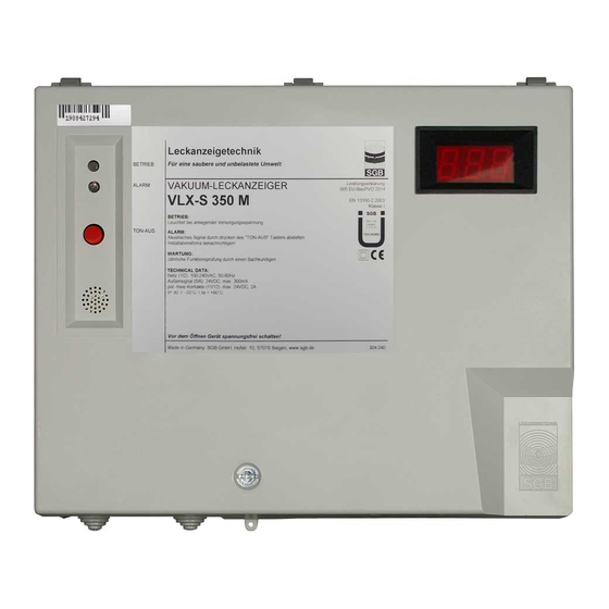
4. Design and function 4.1. System design The VLX-S 350 M leak detector comprises a signalling unit and an installation kit for the tank. The signalling unit features either 1, or 2 – 4 or 5 – 6 display/control panels for the monitoring of 1 – 6 tanks. - Page 11 Display with digital pressure reading Signalling unit of this device version with 6 displays/control panels “Alarm” signal lamp, red “Operation” signal lamp, green “Mute” button Display with digital pressure reading VACUUM LEAK DETECTOR VLX-S 350 M 03/08/2020 - 11 -...
- Page 12 LOD (Leak Online Diag- nosis Service), with: “Alarm” signal lamp, red “Operation” signal lamp, green Terminal strip Buzzer “Mute” button Display circuit board Main circuit board Data transfer module (DTM) VACUUM LEAK DETECTOR VLX-S 350 M 03/08/2020 - 12 -...
- Page 13 Interior view of this device version with four display/control panels, featuring: Terminal strip Buzzer Display circuit board Main circuit board (yellow: 1, red: 2, blue: 3, green: 4) Membrane keypad (yellow: 1, red: 2, blue: 3, green: 4) VACUUM LEAK DETECTOR VLX-S 350 M 03/08/2020 - 13 -...
- Page 14 Interior view of this device version with six display/control panels, featuring: Terminal strip Buzzer Display circuit board Main circuit board (yellow: 1, red: 2, blue: 3, green: 4) Membrane keypad (yellow: 1, red: 2, blue: 3, green: 4) VACUUM LEAK DETECTOR VLX-S 350 M 03/08/2020 - 14 -...
- Page 15 Design and function Installation kit: Installation kit with: Shut-off valve Suction connection (with protective cap) Measurement connection to interstitial space Suction connection to interstitial space Pressure sensor (designed as explosion-proof) VACUUM LEAK DETECTOR VLX-S 350 M 03/08/2020 - 15 -...
-
Page 16: Normal Mode
Before re-commissioning the leak detector, any liquid that has seeped in must be fully channelled off via the suction line. VACUUM LEAK DETECTOR VLX-S 350 M 03/08/2020 - 16 -... -
Page 17: Displays And Controls
Press the button again to switch on the acoustic signal. This function is not available in normal mode or in case of faults. VACUUM LEAK DETECTOR VLX-S 350 M 03/08/2020 - 17 -... -
Page 18: Installing The System
(5) Empty pipes must be laid for feeding the electrical connection line to the tank. Empty pipes must be sealed gas-tight on the tank side in order to prevent the spread of potentially-explosive atmospheres. VACUUM LEAK DETECTOR VLX-S 350 M 03/08/2020 - 18 -... -
Page 19: Sensor
The maximum cable length (for 2 x 0.75 mm shielded cable) be- tween the explosion sensor and the VLX-S 350 M leak detector is 500 m. The sensor cable is shielded. The shielding is not connected to the pressure sensor. -
Page 20: Electrical Cables
(1) Lay firmly, i.e. no plug connections or switch connections. (2) Observe the regulations of the electricity supplier (3) Terminal assignment: (see also 5.9 block diagram) For Germany: VDE regulations also apply VACUUM LEAK DETECTOR VLX-S 350 M 03/08/2020 - 20 -... - Page 21 (2) Insert the cable into the open terminal. (3) Hold the cable tight and remove the screwdriver. (4) Check the seating of the cable and attach the remaining cables using the same principle. VACUUM LEAK DETECTOR VLX-S 350 M 03/08/2020 - 21 -...
-
Page 22: Installation Examples
5.8. Installation examples DIN 6618/2 tank with suction line routed to lowest point Test valve Interstitial space Measuring connection Suction line to lowest point Pressure sensor Hose nipple with screw cap VACUUM LEAK DETECTOR VLX-S 350 M 03/08/2020 - 22 -... - Page 23 Installation Flat-floored tank structures as per DIN 4119 with double floor Test valve Interstitial space Measuring connection Suction line to lowest point Pressure sensor Hose nipple with screw cap VACUUM LEAK DETECTOR VLX-S 350 M 03/08/2020 - 23 -...
- Page 24 Tank as per 66ff with leak protection lining and suction line routed to lowest point Test valve Interstitial space Measuring connection Suction line to lowest point Pressure sensor Hose nipple with screw cap VACUUM LEAK DETECTOR VLX-S 350 M 03/08/2020 - 24 -...
- Page 25 Cellar-welded tank with leak protection lining and suction line routed to lowest point Test valve Interstitial space Measuring connection Suction line to lowest point Pressure sensor Hose nipple with screw cap VACUUM LEAK DETECTOR VLX-S 350 M 03/08/2020 - 25 -...
-
Page 26: Block Diagram
Installation 5.9. Block diagram 5.9.1 VLX-S 350 M block diagram with one display and optionally available DTM “Alarm” signal lamp, red Pressure sensor “Operation” signal lamp, green Display Micro fuse Power supply unit (24 V DC) Relay Membrane keypad Buzzer Contacts for serial data transfer “Mute”... - Page 27 Installation 5.9.2 Block diagram with VLX-S 350 M with 4 displays Buzzer Main circuit board Display Power supply unit (24 V DC) Membrane keypad VACUUM LEAK DETECTOR VLX-S 350 M 03/08/2020 - 27 -...
- Page 28 Installation 5.9.3 Block diagram with VLX-S 350 M with 6 displays Buzzer Main circuit board Display Power supply unit (24 V DC) Membrane keypad VACUUM LEAK DETECTOR VLX-S 350 M 03/08/2020 - 28 -...
-
Page 29: Commissioning
6.1. Interstitial space leak tests (1) Before commissioning the VLX-S 350 M, you must ensure that the connected interstitial spaces are leak-tight. (2) The negative pressure should be built up to 700 mbar using an external pump. -
Page 30: Build-Up Of Negative Pressure Up To Operating Pressure
(LOD service), contact our LOD ser- vice hotline (+49 271 48964-0) after commissioning of the leak detec- tor to set the LOD service up. VACUUM LEAK DETECTOR VLX-S 350 M 03/08/2020 - 30 -... -
Page 31: Functional Check And Maintenance
For Germany: Specialist company, in accordance with German water laws, specialising in leak detector systems For Europe: Authorisation by the manufacturer For Germany: In addition, federal state provisions must be observed (e.g. AwSV) VACUUM LEAK DETECTOR VLX-S 350 M 03/08/2020 - 31 -... - Page 32 Compare with the external measuring device again in order to deter- mine whether the VLX-S 350 M has triggered an alarm at a higher negative pressure level than 350 mbar.
-
Page 33: Alarm
Prevent build-up of electrostatic charges (e.g. from friction). 9.2. Disposal Dispose of contaminated components (possible outgassing) appropri- ately. Dispose of electronic components in the appropriate manner. VACUUM LEAK DETECTOR VLX-S 350 M 03/08/2020 - 33 -... -
Page 34: Spare Parts
Disassembly and disposal 10. Spare parts For spare parts, please refer to our online shop at shop.sgb.de 11. Accessories For accessories, please refer to our online shop at shop.sgb.de VACUUM LEAK DETECTOR VLX-S 350 M 03/08/2020 - 34 -... -
Page 35: Appendix
Appendix 12. Appendix 12.1. Dimensions and drilling pattern (device version 1 up to 4 displays) Spatial requirements for removing housing cover Spatial requirements for opening housing cover VACUUM LEAK DETECTOR VLX-S 350 M 03/08/2020 - 35 -... -
Page 36: Dimensions And Drilling Pattern (Device Version 5 Up To 6 Displays)
Appendix 12.2. Dimensions and drilling pattern (device version 5 up to 6 displays) Depth = 80 mm VACUUM LEAK DETECTOR VLX-S 350 M 03/08/2020 - 36 -... -
Page 37: Eu Declaration Of Conformity
Hofstraße 10 57076 Siegen, Germany under sole responsibility, that the leak detector VLX-S 350 M / VLX-S … M AZ complies with the basic requirements of the EU directives listed be- low. This declaration will become null and void in case of any change to the device not approved by us. -
Page 38: Declaration Of Performance (Dop)
Appendix 12.4 Declaration of performance (DoP) Number: 005 EU-BauPVO 2014 Distinct identification code of the product type: Vacuum leak detector type VLX-S 350 M Intended purpose: Class I vacuum leak detector for monitoring double-walled, un- derground or above-ground, unpressurised tanks Manufacturer: SGB GmbH, Hofstraße 10, 57076 Siegen, Germany... -
Page 39: Certification (Tüv Nord)
Appendix 12.6. Certification (TÜV Nord) VACUUM LEAK DETECTOR VLX-S 350 M 03/08/2020 - 39 -... - Page 40 SGB GmbH Hofstr. 10 57076 Siegen Germany +49 271 48964-0 Photos and dimensions are not binding sgb@sgb.de for the extent of delivery. Subject to VACUUM LEAK DETECTOR VLX-S 350 M 03/08/2020 - 40 - www.sgb.de changes. © SGB GmbH, 08/2020 Text...
Need help?
Do you have a question about the VLX-S 350 M and is the answer not in the manual?
Questions and answers