
Related Manuals for Digi RabbitCore RCM2100 Series


Summary of Contents for Digi RabbitCore RCM2100 Series
- Page 1 RabbitCore RCM2100 Series C-Programmable Modules with Ethernet User’s Manual 019–0091 • 010315–A...
- Page 2 RabbitCore RCM2100 Series: User’s Manual Part Number 019–0091, Rev 010315–A • Printed in U.S.A. © 2001 Z-World, Inc. • All rights reserved. Z-World reserves the right to make changes and improvements to its products without providing notice. Notice to Users...
-
Page 3: Table Of Contents
Introduction 1.1 RabbitCore RCM2100 Series Features ......1-1 1.2 Advantages of the RabbitCore RCM2100 Series..... 1-2 1.3 Development and Evaluation Tools . - Page 4 D.4 D/A Converter ..........D-5 RabbitCore RCM2100 Series...
- Page 5 External Interrupts E.1 Use of External Interrupts........E-2 E.2 Single-Interrupt Request .
- Page 6 RabbitCore RCM2100 Series...
-
Page 7: Introduction 1
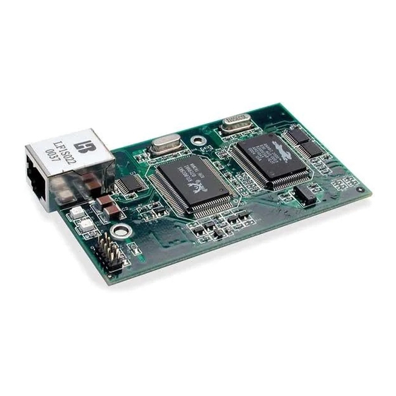
Introduction 1 The RabbitCore RCM2100 series is a family of microprocessor modules designed to be the heart of embedded control systems. In addition to the array of I/O and addressing available on other Z-World products, the RCM2100 series offers an optional integrated Ethernet port. These modules permit LAN and Internet-enabled systems to be built as easily as serial communications- only systems. -
Page 8: Advantages Of The Rabbitcore Rcm2100 Series
Rab- • Five 8-bit timers, two 10-bit timers; five bitCore RCM2100 series. timers are cascadable in pairs Five versions of the RabbitCore RCM2100 series • 2 × 256K flash memory, 512K SRAM are available. Their standard features are summa- •... -
Page 9: How To Use This Manual
In addition to the product-specific information con- plete library of manuals an almost cost-free option. tained in the RabbitCore RCM2100 Series Getting For one-time or infrequent reference, electronic doc- Started and User’s Manual, several higher level uments are more convenient than printed ones—... - Page 10 Print only the sections you will need to charge for a printed and bound manual. refer to more than once. • Print manuals overnight, when appropri- ate, to keep from tying up shared resources during the work day. 1–4 Introduction RabbitCore RCM2100 Series...
-
Page 11: Hardware Reference 2
RabbitCore RCM2100 series. Appendix A, “RabbitCore RCM2100 Specifications,” provides complete physical and electrical specifi- cations. RabbitCore RCM2100 Series Digital Inputs and Outputs Figure 2–1 shows the subsystems designed into the RabbitCore RCM2100 series. PB0– PA0–PA7 PD0–PD7 Ethernet: PD4–PD7... - Page 12 The RabbitCore RCM2100 series has 40 parallel located on pins PA0–PA7, PD0–PD7, and PE0–PE7. I/O lines grouped in five 8-bit ports available on The pinouts for headers J1 and J2 are shown in headers J1 and J2. The 24 bidirectional I/O lines are Figure 2–2.
- Page 13 Table 1: RabbitCore RCM2100 Series Pinout Configurations Pin Name Default Use Alternate Use Notes Disable by removing R20; can also be disabled in PCLK Output (Internal Clock) Output software (Dynamic C 7.03 and later versions) Slave port data bus 4–11...
- Page 14 Table 1: RabbitCore RCM2100 Series Pinout Configurations (continued) Pin Name Default Use Alternate Use Notes Input Serial port clock CLKB CLKA is connected to Input Serial port clock CLKA programming port (header J5, pin 3) Input Slave port write /SWR...
- Page 15 Table 1: RabbitCore RCM2100 Series Pinout Configurations (continued) Pin Name Default Use Alternate Use Notes (0,0)—start executing No programming cable at address zero attached SMODE1, SMODE0 =1, SMODE1 31–32 SMODE0 (0,1)—cold boot from Cold boot from asyn- slave port With programming cable chronous serial port A (1,0)—cold boot from...
-
Page 16: Dedicated Inputs
When the Rabbit 2000 provides the clock, the baud rate can be up to 1/4 of the system clock frequency, or 5.52 Mbps for a 22.1 MHz clock speed. 2–6 Hardware Reference RabbitCore RCM2100 Series... -
Page 17: Ethernet Port
The factory default is for the 0 Ω resistor “jumper” 2.2.2 Ethernet Port at R5 to be installed. In high-noise environments, it Figure 2–3 shows the pinout for the RJ-45 Ethernet may be useful to ground the transformer/connector port (J4). Note that there are two standards for num- assembly directly through the chassis ground. -
Page 18: Programming Port
Serial Port A is also 2.3.1 SRAM the port that is used for software development under The RabbitCore RCM2100 series is designed to Dynamic C. accept 32K to 512K of SRAM packaged in an SOIC The RabbitCore RCM2100 has a 10-pin program case. - Page 19 RCM2100 Factory Default SRAM Flash Memory 128K/256K 512K 128K 512K 3 2 1 3 2 1 Flash EPROM Flash EPROM SRAM Bottom Side Figure 2–6: RabbitCore RCM2100 SRAM and Flash Memory Sizes—Jumper Settings User’s Manual Hardware Reference 2–9...
-
Page 20: Other Hardware
#define CLOCK_DOUBLED 0 // set to 1 to double the clock if XTAL<=12.9MHz, Change the serial baud rate to 57,600 bps when the RabbitCore RCM2100 series is operated at 11.05 MHz. Save the change using File > Save. - Page 21 The battery-backup circuit serves two purposes: when the external power goes off. The switch pro- vides an isolation between Vcc and the battery when • It reduces the battery voltage to the real-time Vcc goes low. This prevents the Vcc line from clock, thereby reducing the current consumed draining the battery.
-
Page 22: Programming Cable
Figure 2–10. The RabbitCore RCM2100 is automatically in pro- gram mode when the PROG connector on the pro- The RabbitCore RCM2100 series is now ready to gramming cable is attached, and is automatically in operate in the run mode. -
Page 23: Software Reference 3
Software Reference 3 Dynamic C Premier is an integrated development system for writing embed- ded software. It runs on an IBM-compatible PC and is designed for use with Z-World controllers and other controllers based on the Rabbit microprocessor. Chapter 3 provides the libraries, function calls, and sample programs related to the RabbitCore RCM2100. -
Page 24: Operating System Framework
The periodic interrupt function also hits the hardware watchdog timer. Software or Flash memory or RAM is selected with the “virtual” watchdog timers are available in 3–2 Software Reference RabbitCore RCM2100 Series... -
Page 25: Dynamic C Libraries
Dynamic C Libraries The sample programs in the Dynamic C SAM- PLES/RCM2100 directory provide further exam- With Dynamic C running, click File > Open, and ples. select Lib. The following list of Dynamic C librar- ies will be displayed. 3.2.2 Serial Communication Drivers The Prototyping Board has room for an RS-232 chip for which the Rabbit serial library, RS232.LIB, provides a set of functions that send and receive... -
Page 26: Tcp/Ip Drivers
Program Mode (see Section 2.5, “Programming Cable”) and must be connected to a PC using the programming cable. More complete information on Dynamic C is pro- vided in the Dynamic C Premier User’s Manual. 3–4 Software Reference RabbitCore RCM2100 Series... -
Page 27: Upgrading Dynamic C
Upgrading Dynamic C ply copy over an entire file since you may overwrite a bug fix; of course, you may copy over any pro- Dynamic C patches that focus on bug fixes are grams you have written. Once you are sure the new available from time to time. - Page 28 3–6 Software Reference RabbitCore RCM2100 Series...
-
Page 29: A Rabbitcore Rcm2100 Specifications
RabbitCore RCM2100 Specifications A Appendix A provides the specifications for the RabbitCore RCM2100, and describes the conformal coating. User’s Manual RabbitCore RCM2100 Specifications A–1... -
Page 30: Electrical And Mechanical Characteristics
Figure A–1). See Section A.1.1, “Headers,” for a “footprint” diagram. Table A–1: RabbitCore RCM2100 Header Pin 1 Locations Pin 1 (x,y) Header Description Coordinates (Inches) RabbitCore RCM2100 subsystems (3.350, 1.730) RabbitCore RCM2100 subsystems (1.000, 1.730) Unisolated Ethernet signals (RCM2115 only) (0.225, 0.860) A–2 RabbitCore RCM2100 Specifications RabbitCore RCM2100 Series... - Page 31 Table A–2 lists the electrical, mechanical, and environmental specifications for the RabbitCore RCM2100. RabbitCore RCM2100 Specifications Table A–2: Parameter Specification 2.00" × 3.50" × 0.80" Board Size (51 mm × 89 mm × 20 mm) Operating Temperature –40°C to +70°C Humidity 5% to 95%, noncondensing Input Voltage...
-
Page 32: Headers
R5 and elected to ground the RJ-45 Ethernet con- nector to the chassis. Table A–3: Capacitance of Rabbit 2000 I/O Ports Input Output I/O Ports Capacitance Capacitance (pF) (pF) Parallel Ports A to E Data Lines BD0–BD7 Address Lines BA0–BA12 A–4 RabbitCore RCM2100 Specifications RabbitCore RCM2100 Series... - Page 33 Figure A–3 shows a typical timing diagram for the Rabbit 2000 microprocessor memory read and write cycles. Memory Read (no wait states) A[19:0] valid T adr T setup D[7:0] valid T hold /CSx valid /OEx Memory Write (no extra wait states) A[19:0] valid T adr...
-
Page 34: Rabbit 2000 Dc Characteristics
CMOS Switching = 5.0 V, 25°C Threshold = See Table A–5 CMOS Output Low (sinking) Voltage = 4.5 V = See Table A–5 CMOS Output High (sourcing) 0.7 x V Voltage = 4.5 V A–6 RabbitCore RCM2100 Specifications RabbitCore RCM2100 Series... -
Page 35: I/O Buffer Sourcing And Sinking Limit
A.4 I/O Buffer Sourcing and per pin. Address pin A0 and data pin D0 are rated at 16 mA each. Pins A1–A12 and D1–D7 are each Sinking Limit rated at 8 mA. The absolute maximum operating Unless otherwise specified, the Rabbit I/O buffers voltage on all I/O is V + 0.5 V, or 5.5 V. -
Page 36: Conformal Coating
Semiconductor Technical Note 303, dures for surface-mounted components. A new con- formal coating should then be applied to offer Conformal Coatings. continuing protection against the effects of mois- ture and contaminants. A–8 RabbitCore RCM2100 Specifications RabbitCore RCM2100 Series... -
Page 37: Power Supply
Power Supply B Appendix B provides information on the current requirements of the RabbitCore RCM2100, and some background on the chip select circuit used in power mange- ment. B.1 Power Supplies The current drain on the battery in a battery-backed circuit must be kept to a minimum. -
Page 38: Chip Select Circuit
This delay is typically very small, about 10 ns SRAM. When power is removed from the circuit, to 15ns. the transistors will turn off and isolate /CSRAM B–2 Power Supply RabbitCore RCM2100 Series... -
Page 39: Programming Cable
Programming Cable C ™ Appendix C provides additional theoretical information for the Rabbit 2000 microprocessor when using the connectors on the program- DIAG PROG ming cable. The connector is used only when the programming cable is PROG attached to the programming connector (header J5) while a new application is being developed. - Page 40 SMODE1 and SMODE0 pins are not con- cold-boot mode has been disabled. nected to this connector. The programming port is then enabled as a diagnostic port by polling the port periodically to see if communication needs to begin C–2 Programming Cable RabbitCore RCM2100 Series...
-
Page 41: D Sample Circuits
Sample Circuits D This appendix details several basic sample circuits that can be used with the RabbitCore RCM2100 series modules. • RS-232/RS-485 Serial Communication • Keypad and LCD Connections • Keypad and LCD Connections • D/A Converter User’s Manual Sample Circuits... -
Page 42: Rs-232/Rs-485 Serial Communication
T1IN T1OUT T2IN T2OUT R1OUT R1IN R2OUT R2IN RabbitCore RCM2100 RS-485 680 W 485+ 220 W 485– 680 W 47 kW SP483EN Figure D–1: Sample RS-232 and RS-485 Circuits Sample Program: PUTS.C in SAMPLES/SERIAL. D–2 Sample Circuits RabbitCore RCM2100 Series... -
Page 43: Keypad And Lcd Connections
D.2 Keypad and LCD Connections RabbitCore RCM2100 10 kW Keypad resistors Row 0 Row 2 Row 3 Row 4 Row 5 Row 1 Col 0 Col 1 Figure D–2: Sample Keypad Connections Sample Program: KEYLCD2.C in SAMPLES/RCM2100. 2x20 LCD RabbitCore RCM2100 Sample LCD Connections Figure D–3:... -
Page 44: External Memory
Rabbit 2000 ports (parallel ports A to E) as address lines. 8K × 8 RabbitCore SRAM RCM2100 BA0–BA12 A0–A12 D0–D7 BD0–BD7 /IOW /IOR 10 kW Figure D–4: Sample External Memory Connections Sample Program: EXTSRAM2.C in SAMPLES/RCM2100. D–4 Sample Circuits RabbitCore RCM2100 Series... -
Page 45: D/A Converter
D.4 D/A Converter The output will initially be 0 V to -10.05 V after the first inverting op-amp, and 0 V to +10.05 V after the sec- ond inverting op-amp. All lows produce 0 V out, FF produces 10 V out. The output can be scaled by chang- ing the feedback resistors on the op-amps. - Page 46 D–6 Sample Circuits RabbitCore RCM2100 Series...
-
Page 47: E External Interrupts
External Interrupts E Appendix E provides information about using the RabbitCore RCM2100 external interrupts. The Rabbit 2000 microprocessor has four external Figure E–1 illustrates these pins. interrupt inputs on Parallel Port E, which is accessed through pins PE0–PE7 on header J2. Table E–1 lists the general-purpose Parallel Port E I/O or INT0A I/O pins that can be used for external interrupts. -
Page 48: Use Of External Interrupts
When the edge detector detects the rising or falling SPURIOUS INTERRUPT edge that it is programmed to detect, it sets a flip- flop that drives the output of the edge detector. The Figure E–3: Interrupt Sequences with Lost or Spurious Interrupts E–2 External Interrupts RabbitCore RCM2100 Series... -
Page 49: Single-Interrupt Request
Single-Interrupt Request Remove R26 and tie the inputs for external interrupt #1 and #0 together by adding a 1 kΩ resistor at R59. Figure E–4 shows the locations of the resistors. Top Side Bottom Side Flash EPROM R58 R59 Figure E–4: Locations of SMT Resistors to Change for External Interrupts Under this configuration, shown in Figure E–5, programmed priority of interrupt #0. -
Page 50: Or'ed Interrupt Request
R23, and install 1 kΩ resistors at R25 and R58. Although Dynamic C Premier does not support this Figure E–4 shows the locations of the resistors. option, an external interrupt may be generated using the RealTek RTL8019AS chip, U3. Remove R22 E–4 External Interrupts RabbitCore RCM2100 Series... - Page 51 Index Dynamic C ......3-1 compile in flash memory or additional information ..1-3 jumper settings RAM option ....3-2 memory size .....2-9 libraries ......3-3 operating system framework 3-2 backup-battery circuit ..2-10 upgrades and patches ..3-5 external battery manuals ........1-3 use ........3-2 connections ....
- Page 52 ....3-4 Run Mode ......2-12 PONG.C ....... 3-4 switching modes .....2-12 Rabbit 2000 timing diagram A-5 RCM2100 ....3-4 relative pin 1 locations ..A-4 TCPIP ......3-4 serial communication drivers 3-3 switching modes ....2-12 Index RabbitCore RCM2100 Series...
- Page 53 Schematics The following schematics are included for user reference: 090–0114 RabbitCore RCM2100 090–0116 RCM2100 Prototyping Board 090–0085 Programming Cable User’s Manual Schematics...
- Page 54 REVISION HISTORY REVISION APPROVAL PROJECT APPROVAL DOCUMENT APPROVAL DESCRIPTION OF CHANGE DATE ENGINEER DATE CONTROL SRAM SRAM select FLASH 1 FLASH 1 select FLASH 2 FLASH 2 select ETHERNET OPTION PORTS D-E OPTION INTERRUPT/JUMPER OPTIONS APPEND THE FOLLOWING DRAWING CONTENT: DOCUMENTS WHEN CHANGING THIS DOCUMENT: 2900 SPAFFORD ST.
- Page 55 NONE...
- Page 56 REVISION APPROVAL REVISION APPROVAL REVISION HISTORY REVISION HISTORY PROJECT PROJECT APPROVAL APPROVAL DOCUMENT DOCUMENT APPROVAL APPROVAL DESCRIPTION DESCRIPTION ENGINEER ENGINEER DATE DATE CONTROL CONTROL DATE DATE APPEND THE FOLLOWING APPEND THE FOLLOWING DRAWING CONTENT: DRAWING CONTENT: DOCUMENTS WHEN CHANGING DOCUMENTS WHEN CHANGING THIS DOCUMENT: THIS DOCUMENT: 2900 SPAFFORD ST.
- Page 57 NONE NONE...
- Page 58 REVISION HISTORY REVISION HISTORY REVISION APPROVAL REVISION APPROVAL PROJECT PROJECT APPROVAL APPROVAL DOCUMENT DOCUMENT APPROVAL APPROVAL DESCRIPTION DESCRIPTION ENGINEER ENGINEER DATE DATE CONTROL CONTROL DATE DATE APPEND THE FOLLOWING APPEND THE FOLLOWING DRAWING CONTENT: DRAWING CONTENT: DOCUMENTS WHEN CHANGING DOCUMENTS WHEN CHANGING THIS DOCUMENT: THIS DOCUMENT: WORLD...
Need help?
Do you have a question about the RabbitCore RCM2100 Series and is the answer not in the manual?
Questions and answers