
Related Manuals for Digi MiniCore RCM5700 Series


Summary of Contents for Digi MiniCore RCM5700 Series
- Page 1 MiniCore RCM5700/RCM6700 C-Programmable Ethernet Core Module User’s Manual 90001191_B Downloaded from Elcodis.com electronic components distributor...
- Page 2 Trademarks Rabbit, MiniCore, and Dynamic C are registered trademarks of Digi International Inc. Wi-Fi is a registered trademark of the Wi-Fi Alliance. Rabbit 5000, Rabbit 6000and MiniCore are trademarks of Digi International Inc.
-
Page 3: Table Of Contents
ABLE OF ONTENTS 1. Introduction 4.4.1 Clocks ..........38 4.4.2 Spectrum Spreader ......38 1.1 RCM5700/RCM6700 Features ......6 4.5 Memory............39 1.2 Advantages of the RCM5700 and RCM6700 8 4.5.1 RAM ............ 39 1.3 Development and Evaluation Tools ....9 4.5.2 Program Flash Memory ....... 39 1.3.1 Standard Development Kit ....9 4.5.3 Mass Storage Serial Flash .... - Page 4 Appendix C. Prototyping Board C.1 Introduction ..........68 C.1.1 Prototyping Board Features ....68 C.2 Mechanical Dimensions and Layout ...69 C.2.1 Headers ..........71 C.3 Using the Prototyping Board .......72 C.3.1 Add Additional Boards .......73 Appendix D. Digital I/O Accessory Board D.1 Introduction ..........75 D.1.1 Digital I/O Accessory Board Features 75 D.2 Mechanical Dimensions and Layout ...76 D.2.1 Headers ..........77...
-
Page 5: Introduction
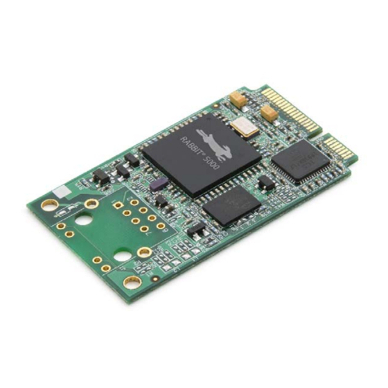
1. I NTRODUCTION The RCM5700 and RCM6700 are compact modules in a mini PCI Express form factor, and incorporate the powerful Rabbit® 5000 and 6000 microprocessors with integrated 10/100Base-T Ethernet func- tionality and onchip SRAM. The Rabbit® 5000 and 6000 microproces- sor features include hardware DMA, I/O lines shared with up to six serial ports and four levels of alternate pin functions that include vari- able-phase PWM, an external I/O bus, quadrature decoder, and input... -
Page 6: Rcm5700/Rcm6700 Features
1.1 RCM5700/RCM6700 Features • Small size: ranges from 1.20" × 2.00" × 0.12" (30 mm × 51 mm × 3 mm) for the RCM5700/ RCM6700 model to 1.20" × 2.00" × 0.73" (30 mm × 51 mm × 19 mm) for the RCM5760/ RCM6760 model •... - Page 7 The RCM5700 and RCM5750 models already have an Ethernet PHY device, the Integrated Cir- cuit Systems ICS1893BK. The RCM5710 and RCM5760 are identical to the RCM5700 and RCM5750 respectively, except that they have an integrated 10/100 Base-T magnetic RJ-45 jack with two LEDs on the MiniCore printed circuit board.
-
Page 8: Advantages Of The Rcm5700 And Rcm6700
All RCM5700/RCM6700 models are programmed through a USB connector on the motherboard using a USB cable supplied with the Development Kit. The RCM5750/RCM5760 may also be programmed remotely over an Ethernet link using the Remote Program Update library with Dynamic C v. 10.56 or later. The RCM67xx series may also be used with the Remote Program Update with Dynamic C v. -
Page 9: Development And Evaluation Tools
1.3 Development and Evaluation Tools 1.3.1 Standard Development Kit The RCM5700/RCM6700 Standard Development Kit contains the hardware essentials you will need to use your RCM5700 or RCM6700 module. These items are supplied in the standard ver- sion of the Development Kit. •... -
Page 10: Software
1.3.3 Software The RCM5700/RCM5710 is programmed using version 10.44 or later of Dynamic C; the RCM5750/RCM5760 requires version 10.56 or later of Dynamic C; and the RCM6700 family requires version 10.64 or later. A compatible version is included on the Development Kit CD-ROM. -
Page 11: Getting Started
2. G ETTING TARTED This chapter describes the RCM5700/RCM6700 hardware in more detail, and explains how to set up and use the accompanying Interface Board. NOTE: This chapter (and this manual) assume that you have the RCM5700/RCM6700 Develop- MiniCore ment Kit. If you purchased an module by itself, you will have to adapt the information in this chapter and elsewhere to your test and development setup. -
Page 12: Hardware Connections
2.2 Hardware Connections There are three steps to connecting the Interface Board for use with Dynamic C and the sample programs: 1. Insert standoffs/connectors on the Interface Board. 2. Install the MiniCore module on the Interface Board. 3. Connect the USB cable between the Interface Board and the workstation PC. 2.2.1 Step 1 —... -
Page 13: Step 2 - Install Module On Interface Board
2.2.2 Step 2 — Install Module on Interface Board Position the MiniCore module with the edge connectors facing the mini PCI Express socket J1A at an angle as shown in Figure 2-3 below. Insert the edge connectors into the mini PCI Express socket J1A, then press down on the opposite edge of the MiniCore module to snap it into place in holder J1B. - Page 14 Should you need to remove the MiniCore module, use two fingernails to hold back the spring clip at J1B from the two MiniCore corners, lift up the edge of the MiniCore above J1B, then pull the MiniCore away to remove the edge connectors from the mini PCI Express socket. CAUTION: ...
-
Page 15: Step 3 - Connect Usb Cable
2.2.3 Step 3 — Connect USB Cable The USB cable connects the RCM5700/RCM6700 to the PC running Dynamic C to download programs and to monitor the MiniCore module during debugging. It also supplies power to the Interface Board and the MiniCore via the USB interface. Connect the USB cable between USB connector J5 on the Interface Board and your PC as shown in Figure 2-4. - Page 16 2.2.3.1 Alternate Power Supply Connections — Deluxe Development Kit The deluxe Development Kit contains a separate AC adapter that may be used to supply power to the Interface Board and the RCM5700/RCM6700 when the USB cable is not connected or when more power is needed than the 500 mA the USB cable is able to supply.
-
Page 17: Starting Dynamic C
2.3 Starting Dynamic C If you already have Dynamic C installed, you are now ready to test your programming connec- tions by running a sample program. Start Dynamic C by double-clicking on the Dynamic C icon on your desktop or in your menu. -
Page 18: Where Do I Go From Here
2.5 Where Do I Go From Here? If the sample program ran fine, you are now ready to go on to other sample programs and to develop your own applications. The source code for the sample programs is provided to allow you to modify them for your own use. -
Page 19: Introduction
3. R UNNING AMPLE ROGRAMS To develop and debug programs for the RCM5700/RCM6700 (and for all other Rabbit hardware), you must install and use Dynamic C. This chapter provides a tour of its major features with respect to the RCM5700/RCM6700. 3.1 Introduction To help familiarize you with the RCM5700/RCM6700 modules, Dynamic C includes several sample programs. -
Page 20: Sample Programs
3.2 Sample Programs Of the many sample programs included with Dynamic C, several are specific to the RCM5700/RCM6700. These programs will be found in the SAMPLES\RCM5700 SAM- folder, depending on your MiniCore model. Sample programs in the PLES\RCM6700 SAMPLES folder one level up are generally generic samples that can be run on any Rabbit-based product Before you compile and run the following sample programs, make sure that pins 1–2, 5–6, and 7–... - Page 21 The Digital I/O accessory board needs to be installed to run the and the SWITCHLEDS.C SERIAL- sample programs. This accessory board is included only with the Deluxe Develop- TOSERIAL.C ment Kit. To install the Digital I/O accessory board, insert the strip of header pins included with the acces- sory board into the socket at J12 on the bottom side of the Digital I/O accessory board.
- Page 22 sample program is in the SERIALTOSERIAL.C SAMPLES\RCM5700\SERIAL folder, depending on your MiniCore model. SAMPLES\RCM6700\SERIAL —monitors switches S1, S2, S3, and S4 on the Digital I/O accessory • SERIALTOSERIAL.C board and lights LEDs DS1–DS4 when the corresponding pushbutton switch is pressed. LEDs DS1–DS2 on the Digital I/O accessory board are controlled by PA4–PA7, and switches S1–S4 are controlled by PB4–PB7 respectively.
- Page 23 The Serial Communication accessory board needs to be installed to run the following serial sam- ple program in the folder, depend- SAMPLES\RCM5700\SERIAL SAMPLES\RCM6700\SERIAL ing on your MiniCore model. This accessory board is included only with the Deluxe Development Kit. To install the Serial Communication accessory board, insert the strip of header pins included with the accessory board into the socket at J12 on the bottom side of the Serial Communication acces- sory board.
-
Page 24: Use Of Serial Flash (Not Supported For Rcm5700/Rcm5710)
Once you have loaded and executed these sample programs and have an understanding of how Dynamic C and the RCM5700/RCM6700 modules interact, you can move on and try the other sample programs, or begin developing your own application. 3.2.1 Use of Serial Flash (not supported for RCM5700/RCM5710) The following sample programs from the SAMPLES\RCM5700\Serial_Flash folder may be used with the RCM5750/RCM5760 models. -
Page 25: Hardware Reference
4. H ARDWARE EFERENCE Chapter 4 describes the hardware components and principal hardware subsys- tems of the RCM5700/RCM6700. Appendix A, “RCM5700/RCM6700 Spec- ifications,” provides complete physical and electrical specifications. Figure 4-8 shows the Rabbit-based subsystems designed into the RCM5700/RCM6700. Figure 4-8. RCM5700/RCM6700 Subsystems rabbit.com MiniCore RCM5700/RCM6700 User’s Manual Downloaded from... -
Page 26: Rcm5700/Rcm6700 Digital Inputs And Outputs
4.1 RCM5700/RCM6700 Digital Inputs and Outputs Figure 4-9 shows the RCM5700/RCM6700 pinouts for the edge connector. Figure 4-9. RCM5700/RCM6700 Pinouts The edge connectors are designed to interface with a 52-pin mini PCI Express socket. Pin 8 has different functionality between the RCM5700 and RCM6700, due to differences in the Ethernet PHY designs. - Page 27 Figure 4-10 shows the use of the Rabbit 5000/6000 microprocessor ports in the RCM5700/ RCM6700 modules. Figure 4-10. Use of Rabbit 5000/6000 Ports The ports on the Rabbit microprocessor used in the RCM5700/RCM6700 are configurable, and so the defaults can be reconfigured. Table 4-3 lists the Rabbit factory defaults and the alternate con- figurations.
- Page 28 Table 4-3. RCM5700/RCM6700 Pinout Configurations Pin Name Default Use Alternate Use Notes +3.3 V Not connected on the RCM5710/5760/6710/6760 Tx– Rx– Requires external pulldown Ethernet on the RCM5700/5750/6700/ 6750 (RCM5700) Requires external pullup on the RCM5700/5750 +2.5V (RCM6700) I/O Strobe I0 Timer C0 Input/Output TCLKF...
- Page 29 Table 4-3. RCM5700/RCM6700 Pinout Configurations Pin Name Default Use Alternate Use Notes I/O Strobe I5 INT1 Input/Output PWM1 RXB/RCLKE Input Capture I/O Strobe I6 PWM2 Input/Output DREQ0 Serial Port E I/O Strobe I7 PWM3 Input/Output RXA/RXE/SCLKC DREQ1 Input Capture /RESET_IN Input Input to Reset Generator I/O Strobe I0...
- Page 30 Table 4-3. RCM5700/RCM6700 Pinout Configurations Pin Name Default Use Alternate Use Notes I/O Strobe I2 Timer C2 Input/Output DREQ0 TXF/SCLKC QRD2B Serial Port F I/O Strobe I3 Timer C3 Input/Output DREQ1 RXC/RXF QRD2A Input Capture I/O Strobe I0 Input/Output Timer C0 TCLKF Serial Port D RXD/TXD...
- Page 31 Table 4-3. RCM5700/RCM6700 Pinout Configurations Pin Name Default Use Alternate Use Notes SCLKB (used by serial flash on RCM5750/RCM5760 and RCM6700 family.) Due to serial boot flash requirements, the RCM6700 SCLKB family’s edge connector pin 27 Input/Output External I/O Address (PB0 / SCLKB) must not be used for general purpose I/O.
- Page 32 Table 4-3. RCM5700/RCM6700 Pinout Configurations Pin Name Default Use Alternate Use Notes STATUS Output Programming port TXA/TXE Input/Output I/O Strobe I6 PWM2 SMODE Input Programming port RXA/TXA/RXE I/O Strobe I7 Input/Output PWM3 SCLKC Input Capture +3.3 V rabbit.com MiniCore RCM5700/RCM6700 User’s Manual Downloaded from Elcodis.com electronic components distributor...
-
Page 33: Memory I/O Interface
4.1.1 Memory I/O Interface The Rabbit 5000 address lines (A0–A19) and data lines (D0–D7) are routed to the onboard flash memory chip. I/O write (/IOWR) and I/O read (/IORD) are available for interfacing to external devices. Parallel Port A can also be used as an external I/O data bus to isolate external I/O from the main data bus. -
Page 34: Serial Communication
4.2 Serial Communication The RCM5700/RCM6700 board does not have any serial level converters directly on the board. However, an Ethernet or other serial interface may be incorporated on the board the MiniCore is mounted on. For example, the Serial Communication accessory board in the Deluxe Development Kit has an RS-232 transceiver, and the Interface Board has Ethernet and USB connections. - Page 35 Table 4-4 summarizes the possible parallel port pins for the serial ports and their clocks. Table 4-4. Rabbit 5000 and 6000 Serial Port and Clock Pins PC6, PC7 PE6, PC6 Serial Port A PC7,PE7 PE7, PC7 Serial Port E SCLKA RCLKE PE5, PC5 PC4, PC5...
-
Page 36: Ethernet Phy
4.2.2 Ethernet PHY All RCM5700/RCM6700 models have an Ethernet PHY, which can either be accessed through the Interface Board or directly on the RCM5710/5760/6710/6760. The PHY connections or inte- grated 10/100Base-T connections on MiniCores with an on-board RJ-45 jack are via 0 jumpers on headers JP2–JP5 (see Table A-6 in Appendix A.3). -
Page 37: Programming Modes
4.3 Programming Modes The USB cable is used to connect the programming port of the RCM5700/RCM6700 to a PC USB port via the Interface Board. Whenever the MiniCore is reset, the operating mode is determined by the state of the SMODE pins. -
Page 38: Standalone Operation Of The Rcm5700/Rcm6700
4.3.1 Standalone Operation of the RCM5700/RCM6700 The RCM5700/RCM6700 must be programmed via the Interface Board or via a similar arrange- ment on a customer-supplied board. Once the MiniCore has been programmed successfully, reset the MiniCore. The MiniCore may be reset by cycling power off/on or by pressing the but- RESET ton on the Interface Board. -
Page 39: Memory
4.5 Memory 4.5.1 RAM RCM5700 boards have 128KB of onchip SRAM on the Rabbit 5000 microprocessor. The RCM5750/RCM5760 models also have 512KB of external SRAM. RCM6700 boards have 1MB of onchip RAM and 32KB of onchip battery-backable SRAM on the Rabbit 6000 microprocessor. -
Page 40: More About Dynamic C
5. S OFTWARE EFERENCE Dynamic C is an integrated development system for writing embedded software. It runs on a Windows-based PC and is designed for use with single-board computers and other devices based on the Rabbit micro- processor. Chapter 5 describes the libraries and function calls related to the RCM5700/RCM6700. - Page 41 Dynamic C has a number of standard features. • Full-feature source and/or assembly-level debugger, no in-circuit emulator required. • Royalty-free TCP/IP stack with source code and most common protocols. • Hundreds of functions in source-code libraries and sample programs: Exceptionally fast support for floating-point arithmetic and transcendental functions. ...
-
Page 42: Dynamic C Function Calls
5.2 Dynamic C Function Calls 5.2.1 Digital I/O The RCM5700/RCM6700 was designed to interface with other systems, and so there are no driv- ers written specifically for the Rabbit 5000/6000 I/O. The general Dynamic C read and write functions allow you to customize the parallel I/O to meet your specific needs. For example, use WrPortI(PEDDR, &PEDDRShadow, 0x00);... -
Page 43: Rcm5700/Rcm6700 Cloning
5.2.4 RCM5700/RCM6700 Cloning The RCM5700/RCM6700 does not have a programming header, and is programmed through the USB connection on the Interface Board. Rabbit’s Cloning Board does not support cloning through a USB connection. If there is a need to copy programs, the Rabbit Field Utility can be used to download compiled Dynamic C .bin files. -
Page 44: Appendix A. Rcm5700/Rcm6700
A. RCM5700/RCM6700 PPENDIX PECIFICATIONS Appendix A provides the specifications for the RCM5700 and RCM6700. rabbit.com MiniCore RCM5700/RCM6700 User’s Manual Downloaded from Elcodis.com electronic components distributor... -
Page 45: Electrical And Mechanical Characteristics
A.1 Electrical and Mechanical Characteristics Figures A-1(a) and A-1(b) show the mechanical dimensions for the RCM5700/RCM6700 and RCM5760/RCM6760. The related dimensions for the RCM5710/6710 and RCM5750/RCM6750 are listed in Table A-1. (All measurements are in inches followed by millimeters enclosed in paren- theses.) Figure A-1(a). - Page 46 Figure A-1(b). RCM5760/RCM6760 Dimensions rabbit.com MiniCore RCM5700/RCM6700 User’s Manual Downloaded from Elcodis.com electronic components distributor...
- Page 47 It is recommended that you allow for an “exclusion zone” of 0.08" (2 mm) around the RCM5700/RCM6700 top and bottom and 0.04" (1 mm) around the three non-connector edges when the RCM5700/RCM6700 is incorporated into an assembly that includes other printed cir- cuit boards.
- Page 48 Table A-1 lists the electrical, mechanical, and environmental specifications for the RCM5700. Table A-1. RCM5700 Specifications Parameter RCM5700 RCM5710 RCM5750 RCM5760 ® Microprocessor Rabbit 5000 at 50.0 MHz EMI Reduction Spectrum spreader for reduced EMI (radiated emissions) 10/100Base-T 10/100Base-T, 10/100Base-T 10/100Base-T, Ethernet Port PHY only...
- Page 49 Table A-1. RCM5700 Specifications Parameter RCM5700 RCM5710 RCM5750 RCM5760 2-channel input capture can be used to time input signals from various port Input Capture pins 2-channel quadrature decoder accepts inputs Quadrature Decoder from external incremental encoder modules 3.15 V DC (min.) – 3.45 V DC (max.) Power 70 mA @ 3.3 V (typical —...
- Page 50 Table A-2 lists the electrical, mechanical, and environmental specifications for the RCM6700. Table A-2. RCM6700 Specifications Parameter RCM6700 RCM6710 RCM6750 RCM6760 ® Microprocessor Rabbit 6000 at 187.5 MHz Spectrum spreader for reduced EMI (radiated emissions) EMI Reduction (when running below 115 MHz) 10/100Base-T 10/100Base-T, 10/100Base-T...
- Page 51 Table A-2. RCM6700 Specifications Parameter RCM6700 RCM6710 RCM6750 RCM6760 2-channel quadrature decoder accepts inputs Quadrature Decoder from external incremental encoder modules 3.15 V DC (min.) – 3.45 V DC (max.) 210 mA @ 3.3V 250 mA @ 3.3V 220 mA @ 3.3V 260 mA @ 3.3V (typical -- with (typical -- with...
-
Page 52: Mini Pci Express Connector Design Recommendations
A.1.1 mini PCI Express Connector Design Recommendations The MiniCore is mounted on the Interface Board via a mini PCI Express connector and a corre- sponding locking latch connector. These are offered by manufacturers as a matched set, although in some cases different manufacturer’s parts may be interchangeable. Table A-3 lists the recom- mended parts for the mini PCI Express connector and the locking latch connector used for the Interface Board. - Page 53 Other manufacturers such as Molex offer similar connectors and latches, but these can have dif- ferent mechanical structures and PCB footprints to what we use on the Interface Board. Table A-4 lists a pair of matched Molex parts that might be used. Table A-4.
-
Page 54: Rabbit 5000 And 6000 Microprocessor Characteristics
Table A-5. Standoff Heights Based on mini PCI Express Connectors mini PCI Express Connector Standoff Height Remarks Height 6.8 mm 4.4 mm Used with Interface Board 9.2 mm 6.8 mm Used with Accessory Kit The SMT connectors are ideal in a development environment, where the latch connector facili- tates swapping MiniCore modules as development progresses. -
Page 55: Jumper Configurations
A.3 Jumper Configurations Figure A-5 shows the header locations used to configure the various RCM5700/RCM6700 options via jumpers. Note that some early versions of the RCM5700 model sold in 2008 and 2009 do not have jumper locations JP2–JP5 — this does not affect the functionality of the RCM5700 model. - Page 56 Table A-7. RCM6700 Jumper Configurations Factory Header Description Pins Connected Default RCM6710/ 1–2 Tx+ to RJ-45 jack (J1) RCM6760 RCM6700/ 2–3 Tx+ to mini PCI Express pins RCM6750 RCM6710/ 1–2 Tx– to RJ-45 jack (J1) RCM6760 Tx– RCM6700/ 2–3 Tx– to mini PCI Express pins RCM6750 RCM6710/ 1–2 Rx–...
-
Page 57: Appendix B. Interface Board
B. I PPENDIX NTERFACE OARD Appendix B describes the features and accessories of the Interface Board, and explains the use of the Interface Board to demonstrate the RCM5700 and RCM6700. The Interface Board has power-supply con- nections and a USB interface to program either MiniCore module. rabbit.com MiniCore RCM5700/RCM6700 User’s Manual Downloaded from... -
Page 58: Introduction
B.1 Introduction The Interface Board included in the Development Kit makes it easy to connect MiniCore module to a power supply and a PC workstation for development. It also provides an Ethernet port. The Interface Board is shown below in Figure B-1, with its main features identified. Figure B-1. -
Page 59: Interface Board Features
B.1.1 Interface Board Features Power Connection —Power is supplied to the Interface Board either from the PC via the USB • connection or through a power supply jack, J6. A chip at U4 disconnects the USB power sup- ply from the rest of the Interface Board when power is supplied through jack J6 Users providing their own power supply should ensure that it delivers +5 V DC at 10 W. -
Page 60: Mechanical Dimensions And Layout
B.2 Mechanical Dimensions and Layout Figure B-2 shows the mechanical dimensions and layout for the Interface Board. All measurements are in inches followed by millimeters enclosed in parentheses. Figure B-2. Interface Board Dimensions Table B-1 lists the electrical, mechanical, and environmental specifications for the Prototyping Board. -
Page 61: Headers
B.2.1 Headers The Interface Board has a header socket at J2 for physical connection to other boards. J2 is a 2 × 25 SMT header socket with a 0.1" pin spacing. Figure B-3 shows the layout of another board to be plugged into the Interface Board — this footprint is identical for the Prototyping Board and the two accessory boards. -
Page 62: Ethernet
B.3 Ethernet B.3.1 RJ-45 The Ethernet filter circuit is different between the Rabbit 5000 and Rabbit 6000 Ethernet designs. If an RJ-45 jack is present on the MiniCore, then the appropriate circuitry is on the MiniCore. If the interface board Ethernet RJ-45 is to be used, then a given interface board will support Ethernet only for either the RCM5700 or RCM6700 family, but not both. -
Page 63: Power Supply
B.4 Power Supply The MiniCore requires a regulated 3.15 V – 3.45 V DC power source to operate. Depending on the amount of current required by the application, different regulators can be used to supply this voltage. The Interface Board has an onboard +3.3 V linear regulator. The Interface Board is protected against reverse polarity by a Shottky diode at D3 as shown in Figure B-4. -
Page 64: Using The Interface Board
B.5 Using the Interface Board The Interface Board is also a demonstration board. It can be used to demonstrate the functionality of the MiniCore right out of the box without any modifications to either board. The Interface Board comes with the basic components necessary to demonstrate the operation of the MiniCore. -
Page 65: Add Additional Boards
B.5.1 Add Additional Boards The Prototyping Board and the two accessory boards included with the Deluxe Development Kit may be installed on the Interface Board as shown in Figure B-6. Figure B-6. Install Additional Boards on Interface Board 1. Insert the header strip into header socket J2 on the Interface Board or the board already installed above the Interface Board. -
Page 66: Interface Board Jumper Configurations
B.6 Interface Board Jumper Configurations Figure B-7 shows the header locations used to configure the various Interface Board options via jumpers. Figure B-7. Location of Configurable Jumpers on Interface Board Table B-3 lists the configuration options using either jumpers or 0 surface-mount resistors. Table B-3. -
Page 67: Appendix C. Prototyping Board
C. P PPENDIX ROTOTYPING OARD Appendix C describes the features and accessories of the Prototyping Board, and explains the use of the Prototyping Board to build proto- types of your own circuits. The Prototyping Board mounts on the Inter- face Board from which it receives its power and signals. rabbit.com MiniCore RCM5700/RCM6700 User’s Manual Downloaded from... -
Page 68: Introduction
C.1 Introduction The Prototyping Board included in the Development Kit provides a prototyping area for more advanced hardware development. The Prototyping Board is shown below in Figure C-1, with its main features identified. Figure C-1. Prototyping Board C.1.1 Prototyping Board Features —Power is supplied to the Prototyping Board via the MiniCore header •... -
Page 69: Mechanical Dimensions And Layout
C.2 Mechanical Dimensions and Layout Figure C-2 shows the mechanical dimensions and layout for the Prototyping Board. Figure C-2. Prototyping Board Dimensions (All measurements are in inches followed by millimeters enclosed in parentheses.) rabbit.com MiniCore RCM5700/RCM6700 User’s Manual Downloaded from Elcodis.com electronic components distributor... - Page 70 Table C-1 lists the electrical, mechanical, and environmental specifications for the Prototyping Board. Table C-1. Prototyping Board Specifications Parameter Specification Board Size 2.50" × 3.75" × 0.52" (64 mm × 95 mm × 13 mm) Operating Temperature –40°C to +85°C Humidity 5% to 95%, noncondensing Operating Voltage...
-
Page 71: Headers
C.2.1 Headers The Prototyping Board has a header socket at J2 for physical connection to other boards above it, and a header socket at J12 on the bottom side to connect to boards below it. J2 and J12 are 2 × 25 SMT header sockets with a 0.1"... -
Page 72: Using The Prototyping Board
C.3 Using the Prototyping Board The Prototyping Board provides the user with MiniCore connection points brought out conveniently to labeled points below header J2. The pinouts for header socket J2 are shown in Figure C-4. Figure C-4. MiniCore Boards Pinout There is a 1.7"... -
Page 73: Add Additional Boards
C.3.1 Add Additional Boards The Prototyping Board and the two accessory boards included with the Deluxe Development Kit may be installed on the Interface Board as shown in Figure C-5. Figure C-5. Install Additional Boards 1. Insert the header strip into header socket J2 on the Interface Board or the board already installed above the Interface Board. - Page 74 D. D I/O A PPENDIX IGITAL CCESSORY OARD Appendix D describes the features and accessories of the Digital I/O accessory board, and explains how to use the Digital I/O accessory board. The Digital I/O accessory board mounts on the Interface Board or other board already installed on the Interface Board from which it receives its power and signals.
-
Page 75: Introduction
D.1 Introduction The Digital I/O accessory board included in the Deluxe Development Kit provides Pushbutton switches and LEDs to use in conjunction with selected sample programs. The Digital I/O acces- sory board is shown below in Figure D-1, with its main features identified. Figure D-1. -
Page 76: Mechanical Dimensions And Layout
D.2 Mechanical Dimensions and Layout Figure D-2 shows the mechanical dimensions and layout for the Digital I/O accessory board. Figure D-2. Digital I/O Accessory Board Dimensions (All measurements are in inches followed by millimeters enclosed in parentheses.) Table D-1 lists the electrical, mechanical, and environmental specifications for the Digital I/O accessory board. -
Page 77: Headers
D.2.1 Headers The Digital I/O accessory board has a header socket at J2 for physical connection to other boards above it, and a header socket at J12 on the bottom side to connect to boards below it. J2 and J12 are 2 ×... -
Page 78: Using The Digital I/O Accessory Board
D.3 Using the Digital I/O Accessory Board The Digital I/O accessory board provides the user with MiniCore connection points brought out conveniently to labeled points below header J2. The pinouts for header socket J2 are shown in Figure D-4. Figure D-4. MiniCore Boards Pinout rabbit.com MiniCore RCM5700/RCM6700 User’s Manual Downloaded from... -
Page 79: Configuration
D.3.1 Configuration The pushbutton switches may be configured active high (pulled down) or active low (pulled up) via jumper settings on header JP7 for the four switches installed. Jumpers on JP12 may be set up in a similar way after additional switches are installed at S5–S8. Figure D-5. - Page 80 Table D-2. Digital I/O Accessory Board Switch/LED Connection Options Connected via Alternate Connection Default MiniCore Switch/LED Signal Header Pins Header 1–2 3–4 5–6 7–8 † 1–2 3–4 JP10 JP11 5–6 7–8 1–2 3–4 JP13 JP14 5–6 7–8 * Switches S1–S4 are pulled high or low via jumpers on header JP7. †...
-
Page 81: Add Additional Boards
D.3.2 Add Additional Boards The Prototyping Board and the two accessory boards included with the Deluxe Development Kit may be installed on the Interface Board as shown in Figure D-7. Figure D-7. Install Additional Boards 1. Insert the header strip into header socket J2 on the Interface Board or the board already installed above the Interface Board. -
Page 82: Accessory Board
E. S PPENDIX ERIAL OMMUNICATION CCESSORY OARD Appendix E describes the features and accessories of the Serial Com- munication accessory board, and explains how to use the Serial Com- munication accessory board. The Serial Communication accessory board mounts on the Interface Board or other board already installed on the Interface Board from which it receives its power and signals. -
Page 83: Introduction
E.1 Introduction The Serial Communication accessory board included in the Deluxe Development Kit provides two 3-wire serial ports to use in conjunction with selected sample programs. The Serial Commu- nication accessory board is shown below in Figure E-1, with its main features identified. Figure E-1. -
Page 84: Mechanical Dimensions And Layout
E.2 Mechanical Dimensions and Layout Figure E-2 shows the mechanical dimensions and layout for the Serial Communication accessory board. (All measurements are in inches followed by millimeters enclosed in parentheses.) Figure E-2. Serial Communication Accessory Board Dimensions Table E-1 lists the electrical, mechanical, and environmental specifications for the Serial Commu- nication accessory board. -
Page 85: Headers
E.2.1 Headers The Serial Communication accessory board has a header socket at J2 for physical connection to other boards above it, and a header socket at J12 on the bottom side to connect to boards below it. J2 and J12 are 2 × 25 SMT header sockets with a 0.1" pin spacing. Figure E-3 shows the layout of another board to be plugged into the Serial Communication accessory board —... -
Page 86: Using The Serial Communication Accessory Board
E.3 Using the Serial Communication Accessory Board The Serial Communication accessory board provides the user with MiniCore connection points brought out conveniently to labeled points below header J2. The pinouts for header socket J2 and the RS-232 headers at J3 and J4 are shown in Figure E-4. Figure E-4. -
Page 87: Configuration
E.3.1 Configuration Serial Ports C and D are brought out as 3-wire RS-232 serial ports on headers J4 and J3 respec- tively. Jumpers may be installed on header JP7 to use header J3 as a 5-wire RS-232 serial port with flow control provided by Serial Port C. Jumpers on headers JP5 connect the MiniCore signals to the RS-232 transceiver. - Page 88 Figure E-5 shows the locations of the configurable header positions. Figure E-5. Location of Configurable Jumpers on Serial Communication Accessory Board rabbit.com MiniCore RCM5700/RCM6700 User’s Manual Downloaded from Elcodis.com electronic components distributor...
-
Page 89: Add Additional Boards
E.3.2 Add Additional Boards The Prototyping Board and the two accessory boards included with the Deluxe Development Kit may be installed on the Interface Board as shown in Figure E-6. Figure E-6. Install Additional Boards 1. Insert the header strip into header socket J2 on the Interface Board or the board already installed above the Interface Board. -
Page 90: Tcp/Ip Connections
F. U TCP/IP F PPENDIX SING THE EATURES F.1 TCP/IP Connections Programming and development can be done with the MiniCore without connecting the Ethernet port to a network. However, if you will be running the sample programs that use the Ethernet capability or will be doing Ethernet-enabled development, you should connect the Ethernet port on the Interface Board at this time. - Page 91 The following options require more care in address selection and testing actions, as conflicts with other users, servers and systems can occur: Connect the Interface Board’s Ethernet port to an existing LAN, preferably one to • LAN — which the development PC is already connected. You will need to obtain IP addressing infor- mation from your network administrator.
-
Page 92: Tcp/Ip Primer On Ip Addresses
F.2 TCP/IP Primer on IP Addresses Obtaining IP addresses to interact over an existing, operating, network can involve a number of complications, and must usually be done with cooperation from your ISP and/or network systems administrator. For this reason, it is suggested that the user begin instead by using a direct connec- tion between a PC and the Interface Board using a CAT 4/5 Ethernet cable or a simple arrange- ment with a hub. - Page 93 If your system administrator can give you an Ethernet cable along with its IP address, the netmask and the gateway address, then you may be able to run the sample programs without having to setup a direct connection between your computer and the MiniCore. You will also need the IP address of the nameserver, the name or IP address of your mail server, and your domain name for some of the sample programs.
-
Page 94: Ip Addresses Explained
F.2.1 IP Addresses Explained IP (Internet Protocol) addresses are expressed as 4 decimal numbers separated by periods, for example: 216.103.126.155 10.1.1.6 Each decimal number must be between 0 and 255. The total IP address is a 32-bit number consist- ing of the 4 bytes expressed as shown above. A local network uses a group of adjacent IP addresses. -
Page 95: How Ip Addresses Are Used
F.2.2 How IP Addresses are Used The actual hardware connection via an Ethernet uses Ethernet adapter addresses (also called MAC addresses). These are 48-bit addresses and are unique for every Ethernet adapter manufac- tured. In order to send a packet to another computer, given the IP address of the other computer, it is first determined if the packet needs to be sent directly to the other computer or to the gateway. -
Page 96: Dynamically Assigned Internet Addresses
F.2.3 Dynamically Assigned Internet Addresses In many instances, devices on a network do not have fixed IP addresses. This is the case when, for example, you are assigned an IP address dynamically by your dial-up Internet service provider (ISP) or when you have a device that provides your IP addresses using the Dynamic Host Config- uration Protocol (DHCP). -
Page 97: Placing Your Device On The Network
F.3 Placing Your Device on the Network In many corporate settings, users are isolated from the Internet by a firewall and/or a proxy server. These devices attempt to secure the company from unauthorized network traffic, and usually work by disallowing traffic that did not originate from inside the network. If you want users on the Internet to communicate with your MiniCore, you have several options. -
Page 98: Running Tcp/Ip Sample Programs
F.4 Running TCP/IP Sample Programs We have provided a number of sample programs demonstrating various uses of TCP/IP for net- working embedded systems. These programs require you to connect your PC and the MiniCore module together on the same network. This network can be a local private network (preferred for initial experimentation and debugging), or a connection via the Internet. -
Page 99: How To Set Ip Addresses In The Sample Programs
F.4.1 How to Set IP Addresses in the Sample Programs With the introduction of Dynamic C 7.30 we have taken steps to make it easier to run many of our sample programs. You will see a macro. This macro tells Dynamic C to select your TCPCONFIG configuration from a list of default configurations. -
Page 100: How To Set Up Your Computer For Direct Connect
F.4.2 How to Set Up your Computer for Direct Connect Follow these instructions to set up your PC or notebook. Check with your administrator if you are unable to change the settings as described here since you may need administrator privileges. The instructions are specifically for Windows 2000, but the interface is similar for other versions of Windows. -
Page 101: Run The Pingme.c Sample Program
F.5 Run the PINGME.C Sample Program Connect the crossover cable from your computer’s Ethernet port to the MiniCore module’s RJ-45 Ethernet connector. Open this sample program from the folder, compile SAMPLES\TCPIP\ICMP the program, and start it running under Dynamic C. The crossover cable is connected from your computer’s Ethernet adapter to the MiniCore module’s RJ-45 Ethernet connector. -
Page 102: Running Additional Sample Programs With Direct Connect
F.6 Running Additional Sample Programs With Direct Connect The sample programs discussed here are in the Dynamic C SAMPLES\RCM5700\TCPIP\ SAM- folder. PLES\RCM6700\TCPIP —The Digital I/O accessory board must be installed with the jumpers set up as • BROWSELED.C shown below to run this sample program. This program demonstrates a basic controller running a Web page. -
Page 103: Where Do I Go From Here
115200 Bits per second: Data bits: 8 Parity: None Stop bits: 1 Flow control: None As long as you have not modified the macro in the sample program, enter the TCPCONFIG 1 following server address in your Web browser to bring up the Web page served by the sample program. -
Page 104: Appendix G. Power Supply
G. P PPENDIX OWER UPPLY Appendix G provides information on the current requirements of the RCM5700/RCM6700, and includes some background on the chip select circuit used in power management. G.1 Power Supplies The RCM5700/RCM6700 requires a regulated 3.15 V – 3.45 V DC power source. The MiniCore design presumes that the voltage regulator is on the user board, and that the power is made avail- able to the RCM5700 board through the edge connectors. -
Page 105: Battery Backup For The Rcm5700/Rcm5710 And Rcm6700 Family
G.1.1 Battery Backup for the RCM5700/RCM5710 and RCM6700 Family The RCM5700/RCM6700 does not have a battery, but there is provision for a customer-supplied battery to keep the internal Rabbit 5000/6000 real-time clock running on the RCM5700/RCM5710 and RCM6700 family of modules. Battery Backup is not available on the RCM5750/5760 modules. -
Page 106: Battery-Backup Circuit
The actual life in your application will depend on the current drawn by components not on the RCM5700/RCM6700 and on the storage capacity of the battery. The RCM5700/RCM6700 does not drain the battery while it is powered up normally. Cycle the main power off/on on the MiniCore after you install a backup battery for the first time, and whenever you replace the battery. - Page 107 NDEX USB cable ............9 digital I/O ..............26 accessory boards function calls ............42 Digital I/O ............75 memory interface ..........33 configuration options ........79 SMODE0 ............. 33 LED outputs ..........79 SMODE1 ............. 33 pushbutton switches ........79 Digital I/O accessory board ......74, 75 dimensions ............76 features ..............
- Page 108 Digital I/O accessory board .........78 Ethernet port ............36 features RCM5700 Digital I/O accessory board .........75 alternate configurations ........28 Interface Board ............59 RCM5700 edge connectors .........26 Prototyping Board ..........68 Serial Communication accessory board ....86 RCM5700 ..............6 power supplies Serial Communication accessory board ....83 +3.3 V ..............104 battery backup ...........105 Program Mode ............37...
- Page 109 ETHERNET_TO_SERIAL.C ......102 PINGME.C ...........101 tamper detection ............39 USERBLOCK_CLEAR.C ........42 TCP/IP primer ............92 USERBLOCK_INFO.C ........42 technical support .............18 serial communication ..........34 troubleshooting ............17 function calls ............42 software PACKET.LIB ..........42 RS232.LIB ............42 USB cable Serial Communication accessory board ....83 connections ............15 features ..............83 user block serial flash function calls ............42...
- Page 110 rabbit.com MiniCore RCM5700/6700 User’s Manual Downloaded from Elcodis.com electronic components distributor...
- Page 111 rabbit.com MiniCore RCM5700/6700 User’s Manual Downloaded from Elcodis.com electronic components distributor...
- Page 112 rabbit.com MiniCore RCM5700/6700 User’s Manual Downloaded from Elcodis.com electronic components distributor...
- Page 113 rabbit.com MiniCore RCM5700/6700 User’s Manual Downloaded from Elcodis.com electronic components distributor...
- Page 114 rabbit.com MiniCore RCM5700/6700 User’s Manual Downloaded from Elcodis.com electronic components distributor...
- Page 115 rabbit.com MiniCore RCM5700/6700 User’s Manual Downloaded from Elcodis.com electronic components distributor...
- Page 116 rabbit.com MiniCore RCM5700/6700 User’s Manual Downloaded from Elcodis.com electronic components distributor...
- Page 117 rabbit.com MiniCore RCM5700/6700 User’s Manual Downloaded from Elcodis.com electronic components distributor...
- Page 118 rabbit.com MiniCore RCM5700/6700 User’s Manual Downloaded from Elcodis.com electronic components distributor...
- Page 119 rabbit.com MiniCore RCM5700/6700 User’s Manual Downloaded from Elcodis.com electronic components distributor...
Need help?
Do you have a question about the MiniCore RCM5700 Series and is the answer not in the manual?
Questions and answers