Vega VEGAPULS 66 Operating Instructions Manual
Foundation fieldbus standpipe version
Hide thumbs
Also See for VEGAPULS 66:
- Operating instructions manual (88 pages) ,
- Quick setup manual (24 pages) ,
- Safety instruction (16 pages)

Related Manuals for Vega VEGAPULS 66


Summary of Contents for Vega VEGAPULS 66
- Page 1 Operating Instructions VEGAPULS 66 Foundation Fieldbus Standpipe version Document ID: 28744...
-
Page 2: Table Of Contents
6.10 Saving the parameterisation data ................... 39 Set up with PACTware and other adjustment programs ............ 40 Connect the PC ......................40 Parameter adjustment with PACTware ................41 7.3 Parameter adjustment with AMS™................. 42 Saving the parameterisation data ................... 42 8 Maintenance and fault rectification ..................43 VEGAPULS 66 • Foundation Fieldbus... - Page 3 10.4 Industrial property rights ....................59 10.5 Trademark ........................59 Safety instructions for Ex areas Take note of the Ex specific safety instructions for Ex applications. These instructions are attached as documents to each instrument with Ex approval and are part of the operating instructions. Editing status: 2018-12-18 VEGAPULS 66 • Foundation Fieldbus...
-
Page 4: About This Document
Symbols used Document ID This symbol on the front page of this instruction refers to the Docu- ment ID. By entering the Document ID on www.vega.com you will reach the document download. Information, tip, note This symbol indicates helpful additional information. -
Page 5: For Your Safety
During work on and with the device, the required personal protective equipment must always be worn. Appropriate use VEGAPULS 66 is a sensor for continuous level measurement. You can find detailed information about the area of application in chapter "Product description". Operational reliability is ensured only if the instrument is properly used according to the specifications in the operating instructions manual as well as possible supplementary instructions. -
Page 6: Safety Label On The Instrument
For operation inside of closed vessels, points a to f in annex E of EN 302372 must be fulfilled. FCC and IC conformity (only for USA/Canada) VEGAPULS 66 is FCC and IC approved: • FCC ID: O6QPULS6566 • IC: 3892A-PS6566... -
Page 7: Installation And Operation In The Usa And Canada
2 For your safety Modifications not expressly approved by VEGA will lead to expiry of the operating licence according to FCC. VEGAPULS 66 is in conformity with part 15 of the FCC regulations. Take note of the respective operating regulations: • This device may not cause interference, and • The device must be resistant to interference signals, including... -
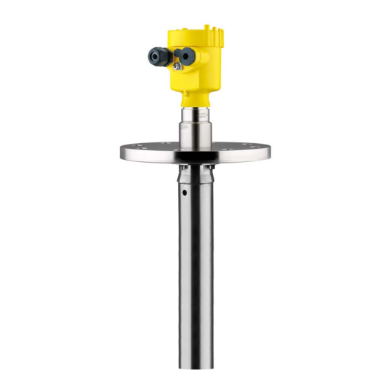
Page 8: Product Description
In this operating instructions manual, the optional instrument features are described. The respective scope of delivery results from the order specification. Constituent parts The VEGAPULS 66 consists of the components: • Process fitting with standpipe antenna • Housing with electronics, optionally available with plug connector, optionally available with connection cable •... - Page 9 3 Product description Fig. 1: VEGAPULS 66, flange version up to 150 °C with plastic housing Housing cover with integrated PLICSCOM (optional) Housing with electronics Process fitting with standpipe antenna Type label The type label contains the most important data for identification and use of the instrument: • Instrument type •...
-
Page 10: Principle Of Operation
Application area VEGAPULS 66 is a radar sensor in C-band (emitting frequency ap- prox. 6 GHz) for continuous level measurement. A special version of VEGAPULS 66 is available for each area of ap- plication. The version with flange and standpipe is particularly suitable for the measurement of solvents and liquid gases. The standpipe antenna is also suitable for vessels with foam gen- eration or for measurement of products with low dielectric figures (DK >... -
Page 11: Packaging, Transport And Storage
• PC/notebook with Bluetooth USB adapter (Windows operating system) You can find further information in the operating instructions "Display and adjustment module PLICSCOM" (Document-ID 36433). VEGACONNECT The interface adapter VEGACONNECT enables the connection of communication-capable instruments to the USB interface of a PC. For VEGAPULS 66 • Foundation Fieldbus... - Page 12 You can find further information in the operating instructions "Interface adapter VEGACONNECT" (Document-ID 32628). VEGADIS 81 The VEGADIS 81 is an external display and adjustment unit for VEGA plics sensors. ® For sensors with double chamber housing the interface adapter "VEGADIS adapter"...
-
Page 13: Mounting
Prior to setup you have to replace these protective caps with ap- proved cable glands or close the openings with suitable blind plugs. Measuring range The reference plane for the measuring range is the lower edge of the flange or the seal surface of the thread. The measuring range extends VEGAPULS 66 • Foundation Fieldbus... - Page 14 The emitted radar impulses of VEGAPULS 66 are electromagnetic Polarisation plane waves. The polarisation plane is the direction of the electrical share. Their position is marked on the instrument. Fig. 4: Position of the polarisation plane of VEGAPULS 66 Marking hole Suitability for the process Make sure that all parts of the instrument coming in direct contact...
-
Page 15: Mounting Instructions
Take care that the plastic tip of the radar sensor is not damaged during transport. Fig. 5: Polarisation marking Marking of the polarisation direction Vent hole ø 8 mm (0.3 in) Inflowing medium Do not mount the instruments in or above the filling stream. Fig. 6: Inflowing liquid VEGAPULS 66 • Foundation Fieldbus... -
Page 16: Connecting To Power Supply
The cable screens to the power supply unit and to the next distributor must be connected to each other and also connected to ground potential via a ceramic capacitor (e.g. 1 nF, 1500 V). The low frequency potential equalisation currents are thus suppressed, VEGAPULS 66 • Foundation Fieldbus... -
Page 17: Connection Procedure
Fig. 7: Connection steps 6 and 7 8. Press down the opening levers of the terminals, you will hear the terminal spring closing 9. Check the hold of the wires in the terminals by lightly pulling on them VEGAPULS 66 • Foundation Fieldbus... -
Page 18: Wiring Plan, Single Chamber Housing
Fig. 8: Material versions, single chamber housing Plastic Aluminium Stainless steel (precision casting) Stainless steel (electro-polished) Filter element for air pressure compensation of all material versions. Blind plug with version IP 66/IP 68, 1 bar for Aluminium and stainless steel VEGAPULS 66 • Foundation Fieldbus... -
Page 19: Wiring Plan, Double Chamber Housing
Display I 2 C Fig. 10: Wiring plan - single chamber housing Voltage supply, signal output Wiring plan, double chamber housing The following illustrations apply to the non-Ex as well as to the Ex-ia version. VEGAPULS 66 • Foundation Fieldbus... - Page 20 Fig. 12: Electronics compartment - double chamber housing Simulation switch ("on" = simulation mode) Spring contacts for display and adjustment module Interface for service Internal connection cable to the connection compartment Ground terminal for connection of the cable screening VEGAPULS 66 • Foundation Fieldbus...
-
Page 21: Wiring Plan, Ex-D Double Chamber Housing
Ground terminal for connection of the cable screening Wiring plan I 2 C Fig. 14: Wiring plan - double chamber housing Voltage supply, signal output Wiring plan, Ex-d double chamber housing Information: Instruments in Ex d version with hardware revision …- 01 or higher as well as with national approvals such as e.g. according to FM or CSA at a later date. VEGAPULS 66 • Foundation Fieldbus... - Page 22 Fig. 16: Electronics compartment - double chamber housing Simulation switch ("on" = simulation mode) Spring contacts for display and adjustment module Interface for service Internal connection cable to the connection compartment Ground terminal for connection of the cable screening VEGAPULS 66 • Foundation Fieldbus...
-
Page 23: Wiring Plan - Version Ip 66/Ip 68, 1 Bar
Voltage supply, signal output Wiring plan - version IP 66/IP 68, 1 bar Wire assignment, con- nection cable Fig. 19: Wire assignment, connection cable Brown (+) and blue (-) to power supply or to the processing system Shielding VEGAPULS 66 • Foundation Fieldbus... -
Page 24: Switch-On Phase
5 Connecting to power supply Switch-on phase Switch-on phase After VEGAPULS 66 is connected to voltage supply or after voltage recurrence, the instrument carries out a self-check for approx. 30 seconds. The following steps are carried out: • Internal check of the electronics •... -
Page 25: Set Up With The Display And Adjustment Module Plicscom
4. Screw housing lid with inspection window tightly back on Disassembly is carried out in reverse order. The display and adjustment module is powered by the sensor, an ad- ditional connection is not necessary. VEGAPULS 66 • Foundation Fieldbus... -
Page 26: Adjustment System
Fig. 21: Display and adjustment elements LC display Indication of the menu item number Adjustment keys • Key functions [OK] key: – Move to the menu overview – Confirm selected menu – Edit parameter – Save value • [->] key to select: – Menu change VEGAPULS 66 • Foundation Fieldbus... -
Page 27: Setup Steps
For indication of the real level, an allocation of the measured distance to the percentage height must be carried out. 100% Fig. 22: Parameterization example Min. level = max. measuring distance Max. level = min. measuring distance Reference plane VEGAPULS 66 • Foundation Fieldbus... - Page 28 2. Enter the appropriate distance value in m (corresponding to the percentage value) for the full vessel. Keep in mind that the max. level must lie below the dead band. 3. Save the settings with [OK] and move to "Medium selection" with [->]. VEGAPULS 66 • Foundation Fieldbus...
- Page 29 "Solid". Medium Liquid Information: With VEGAPULS 66 with electronics version "Increased safety", "Solid" is preset as factory setting. However, the instrument should be used preferably in liquids. In such cases, the medium selection should be set to "Liquid" during setup.
- Page 30 Enter the requested parameters via the appropriate keys, save your settings and jump to the next menu item with the [->] key. Caution: Note the following if the VEGAPULS 66 with corresponding approval is used as part of an overfill protection system according to WHG (Water Resources Act): If a linearisation curve is selected, the measuring signal is no longer necessarily linear to the filling height. This must be considered by the...
- Page 31 A comparison of the echo curve and the false echo curve allows a entation more detailled evaluation of measurement reliability. The selected curve is updated continuously. With the [OK] key, a submenu with zoom functions is opened. The following functions are available with "Echo and false echo curve": VEGAPULS 66 • Foundation Fieldbus...
- Page 32 Check the distance to the product surface, because if an incorrect (too large) value is entered, the existing level will be saved as a false signal. The level would then no longer be detectable in this area. VEGAPULS 66 • Foundation Fieldbus...
- Page 33 The menu item "Extended setting" offers the possibility to optimise Service - Extended set- ting VEGAPULS 66 for applications in which the level changes very quickly. To do this, select the function "Quick level change > 1 m/min.". Extended setting quick level change > 1 m/min.
- Page 34 The min. and max. distance values are reset to the actual value. Service - Adjustment unit In this menu item you select the internal arithmetic unit of the sensor. Sensor-specific basic adjustment. Special parameters are parameters which are set customer-specifically on the service level with the adjustment software PACTware. VEGAPULS 66 • Foundation Fieldbus...
- Page 35 Unit of measurement • Language The following safety-relevant data are not read out or written: • Copy sensor data Copy sensor data? Service - PIN In this menu item, the PIN is activated/deactivated permanently. Entering a 4-digit PIN protects the sensor data against unauthorized With standpipe versions. VEGAPULS 66 • Foundation Fieldbus...
- Page 36 PC Last change using PC • Device-ID • Sensor-TAG Device ID < max. 32 characters > Sensor-TAG (PD_TAG) < max. 32 characters > • Sensor details, e.g. approval, process fitting, seal, measuring cell, measuring range, electronics, housing, cable entry, plug, cable length etc. VEGAPULS 66 • Foundation Fieldbus...
-
Page 37: Menu Schematic
0.00 % 100.00 % Liquid ▼ not known 30.000 m(d) 0.000 m(d) 0.665 m(d) 0.665 m(d) Linearisation curve Sensor-TAG ▼ Sensor linear Display Basic adjustment ▶ Display Diagnostics Service Info Displayed value Backlight ▼ AI-Out Switched off VEGAPULS 66 • Foundation Fieldbus... - Page 38 Copy sensor data ▼ ▼ Reset now? Copy sensor data? m(d) Deutsch Enable? Info Basic adjustment Display Diagnostics Service ▶ Info Instrument type Date of manufacture Last change using PC Sensor characteristics Software version Display now? Serial number VEGAPULS 66 • Foundation Fieldbus...
-
Page 39: Saving The Parameterisation Data
They are thus available for multiple use or service purposes. If VEGAPULS 66 is equipped with a display and adjustment module, the most important data can be read out of the sensor into the display and adjustment module. -
Page 40: Set Up With Pactware And Other Adjustment Programs
Sensor VEGACONNECT exter- nally TWIST Fig. 24: Connection via VEGACONNECT externally I²C bus (com.) interface on the sensor I²C connection cable of VEGACONNECT VEGACONNECT USB cable to the PC Necessary components: • VEGAPULS 66 • PC with PACTware and suitable VEGA DTM VEGAPULS 66 • Foundation Fieldbus... -
Page 41: Parameter Adjustment With Pactware
Saving/printing the project as well as import/export functions are also part of the standard version. In the full version there is also an extended print function for complete project documentation as well as a save function for measured value VEGAPULS 66 • Foundation Fieldbus... -
Page 42: Parameter Adjustment With Ams
The standard version is available as a download under www.vega.com/downloads. The full version is available on CD from the agency serving you. Parameter adjustment with AMS™... -
Page 43: Maintenance And Fault Rectification
24 hour service hotline Should these measures not be successful, please call in urgent cases the VEGA service hotline under the phone no. +49 1805 858550. The hotline is manned 7 days a week round-the-clock. Since we offer this service worldwide, the support is only available in the English language. The service is free, only standard call charges are incurred. -
Page 44: Exchanging The Electronics Module
Ex approval may be used. If there is no electronics module available on site, one can be ordered from the VEGA agency serving you. Sensor serial number The new electronics module must be loaded with the settings of the sensor. -
Page 45: Software Update
Clean the instrument and pack it damage-proof • Attach the completed form and, if need be, also a safety data sheet outside on the packaging • Please contact the agency serving you to get the address for the return shipment. You can find the agency on our home page www.vega.com. VEGAPULS 66 • Foundation Fieldbus... -
Page 46: Dismount
Pass the instrument directly on to a specialised recycling company and do not use the municipal collecting points. If you have no way to dispose of the old instrument properly, please contact us concerning return and disposal. VEGAPULS 66 • Foundation Fieldbus... -
Page 47: Supplement
Foundation Fieldbus protocol Ʋ Physical layer according to IEC 61158-2 Cycle time min. 1 s (dependent on the parameter setting) Ʋ Damping (63 % of the input variable) 0 … 999 s, adjustable Ʋ Met NAMUR recommendation NE 43 Glass with Aluminium and stainless steel precision casting housing VEGAPULS 66 • Foundation Fieldbus... - Page 48 Ʋ Pulse duration < 2 ns Ʋ SAR value 0.471 mW/kg Deviation (according to DIN EN 60770-1) Deviation ≤ 5 mm (meas. distance > 0.5 m/1.640 ft) According to the respective standpipe length. Time to output the correct level (with max. 10 % deviation) after a sudden level change. At the aperture of a horn antenna with ø 150 mm. Incl. non-linearity, hysteresis and non-repeatability. VEGAPULS 66 • Foundation Fieldbus...
- Page 49 - 5 mm (- 0.197 in) 5,85 m 0,5 m (19.19 ft) (1.6 ft) - 10 mm (- 0.394 in) Fig. 26: Deviation VEGAPULS 66 standpipe Influence of the ambient temperature to the sensor electronics Average temperature coefficient of the < 0.03 %/10 K zero signal (temperature error) Influence of the superimposed gas and pressure on measurement accuracy The spreading speed of the radar impulses in gas or vapour above the product is reduced by high pressures. This effect depends on the superimposed gas or vapour and increases with low tem-...
- Page 50 25 mm (0.984 in) with 25 °C (77 °F) Ʋ Diameter approx. 8 mm (0.315 in) Ʋ Colour - Non-Ex version Black Ʋ Colour - Ex-version Blue Tested according to the guidelines of German Lloyd, GL directive 2. VEGAPULS 66 • Foundation Fieldbus...
- Page 51 Type 6P IP 68 (1 bar) Type 6P Double chamber IP 66/IP 67 Type 4X IP 66/IP 68 (0.2 bar) Type 6P IP 68 (1 bar) Type 6P Galvanic separation between electronics and metal housing parts VEGAPULS 66 • Foundation Fieldbus...
-
Page 52: Foundation Fieldbus
Instruments with approvals can have different technical specifications depending on the version. For that reason the associated approval documents of these instruments have to be carefully noted. They are part of the delivery or can be downloaded under www.vega.com, "Instrument search (serial number)" as well as in the general download area. - Page 53 AI 1 Channel = 1: Primary Value AI 2 Channel = 2: Secondary Value 1 Channel = 3: Secondary Value 2 Fig. 27: VEGAPULS 66 measured value processing Diagram, adjustment The following illustration shows the function of the adjustment. Secondary_value_1 cal_level_hi...
- Page 54 – Holds the maximum sensor value. Write access resets to current value. Unit derives from 'Sen- sor_range.unit' • min_peak_sensor_value – Holds the minimum sensor value. Write access resets to current value. Unit derives from 'Sen- sor_range.unit' • Calibration Highest Point – Min./max.-adjustment: Upper calibrated point of the sensor. It refers to 'Cal_level_hi'. The unit is defined in 'Sensor_range.unit' • Calibration Lowest Point – Min./max.-adjustment: Lower calibrated point of the sensor. It refers to 'Cal_level_lo'. The unit is defined in 'Sensor_range.unit' VEGAPULS 66 • Foundation Fieldbus...
- Page 55 – Distance from the sensor to the product surface. Unit derives from 'Sensor_range.unit' • empty_vessel_curve_corr_op_code – Update, create new or delete the empty vessel curve • tube diameter – Set up to suit the process conditions VEGAPULS 66 • Foundation Fieldbus...
-
Page 56: Dimensions
10 Supplement 10.3 Dimensions The following dimensional drawings represent only an extract of all possible versions. Detailed dimensional drawings can be downloaded at www.vega.com/downloads under "Drawings". Plastic housing ~ 69 mm ~ 84 mm (2.72") (3.31") ø 79 mm ø 79 mm (3.11") - Page 57 1 is 9 mm/0.35 in higher, with position 2 18 mm/0.71 in) Stainless steel single chamber (electropolished) Stainless steel single chamber (precision casting) Stainless steel double chamber housing (precision casting) VEGAPULS 66 • Foundation Fieldbus...
- Page 58 ø 56 mm (2.21") ø 52 mm (2.05") Fig. 34: VEGAPULS 66, standpipe version Standard version For process temperatures up to 250 °C (482 °F) For process temperatures up to 400 °C (752 °F) The plant operator must provide a suitable support for the standpipe depending on the length and the process conditions.
-
Page 59: Industrial Property Rights
Les lignes de produits VEGA sont globalement protégées par des droits de propriété intellec- tuelle. Pour plus d'informations, on pourra se référer au site www.vega.com. VEGA lineas de productos están protegidas por los derechos en el campo de la propiedad indus- trial. Para mayor información revise la pagina web www.vega.com. - Page 60 Subject to change without prior notice © VEGA Grieshaber KG, Schiltach/Germany 2019 VEGA Grieshaber KG Phone +49 7836 50-0 Am Hohenstein 113...
Need help?
Do you have a question about the VEGAPULS 66 and is the answer not in the manual?
Questions and answers