
Subscribe to Our Youtube Channel
Related Manuals for W&T IP-Watcher 2x2 Digital PoE


Summary of Contents for W&T IP-Watcher 2x2 Digital PoE
- Page 1 Manual IP-Watcher 2x2 Digital PoE IP-Watcher 2x2 Digital W&T Modell #57655 Release EN 3.19 08/2010 PA...
- Page 2 W&T © 08/2010, Wiesemann & Theis GmbH Microsoft, MS-DOS, Windows, Winsock und Visual Basic are registered trademarks of Microsoft Corporation. Subject to errors and changes: Since we can make errors, none of our information should be used without verification. Please inform us of any mistakes or misunderstandings so that we can detect and eliminate them as quickly as possible..
- Page 3 W&T...
-
Page 4: Table Of Contents
W&T Contents 1. Introduction ..............8 2. Startup ................9 2.1 Supply voltage ..............9 2.1.1 External supply voltage ..........9 2.1.2 Voltage supply using PoE ..........10 2.2 Network connection ............10 2.3 Wiring the inputs............11 2.4 Wiring the outputs ............12 2.5 Assigning the IP address using Wutility ...... - Page 5 W&T 4.4.2 Mail parameters and texts ........... 46 4.5 Alarming per SNMP trap ..........46 4.5.1 General settings ............47 4.5.2 SNMP parameters and texts ......... 47 4.6 Alarming per Syslog ............48 4.6.1 General settings ............49 4.6.2 Syslog parameters and texts ........49 4.7 Alarming per FTP............
- Page 6 W&T 8.1.2 Status-LED ..............73 8.1.3 Error-LED ..............73 8.2 Factory defaults ............74 8.2.1 Web-Based Management ..........74 8.2.2 Reset jumpers ............74 8.3 Alternative IP address assignment ........75 8.3.1 ARP command ............75 8.3.2 RARP server (UNIX only) ..........76 8.4 Firmware update ............
- Page 7 W&T...
-
Page 8: Introduction
W&T IP-Watcher 2x2 Digital PoE 1. Introduction The IP Watcher from W&T uses cyclical polling to monitor network components. If a device no longer responds, this status can be reported by triggering local or remote alarms. Local alarms indicate non-response by switching a connected consumer on one of the two digital outputs. -
Page 9: Startup
W&T IP-Watcher 2x2 Digital PoE 2. Startup Just a few steps are needed to incorporate the IP-Watcher into your network and get it running. 2.1 Supply voltage The following describes the two methods of providing power to the IP-Watcher. The types of voltage supply described here provide only power to the device. -
Page 10: Voltage Supply Using Poe
W&T IP-Watcher 2x2 Digital PoE The external supply voltage for the device is always required in networks not providing PoE, but may also be used in PoE environments. When powering with DC voltage, correct polarity is not required. It is also possible to power the device with 12V DC. There however you must take into account the very poor efficiency of the power supply and the associated elevated current draw. -
Page 11: Wiring The Inputs
W&T IP-Watcher 2x2 Digital PoE The factory default setting for the IP-Watcher on the network side is for Auto-Negotiation. Data transmission speed and duplex procedure are automatically negotiated with the connected switch/hub and set appropriately. The network connection is galvanically isolated to 1kV with respect to the power supply as well as the digital IOs. -
Page 12: Wiring The Outputs
W&T IP-Watcher 2x2 Digital PoE If you need to use the inputs for monitoring the states of po- tential-free contacts, the supply voltage for the unit can also be used as the signal voltage. In this case you need to operate the IP-Watcher with a DC voltage of 12V-30V. -
Page 13: Assigning The Ip Address Using Wutility
W&T IP-Watcher 2x2 Digital PoE supply for supplying the outputs as well, but use no more than 30V for powering the device. In the configuration you can set up, to give the power supply of the IP-Watcher directly to the terminals Vdd and GND. In this case an external supply for the IOs is not required. - Page 14 W&T IP-Watcher 2x2 Digital PoE WuTility with found W&T network device Use the button IP address to go to the configuration dialog box. There you enter the desired network parameters for the device. Confirm your entry by clicking on the Next button:...
-
Page 15: Automatic Ip Address Assignment
W&T IP-Watcher 2x2 Digital PoE Configuration dialog box for address assigning By clicking on the Next button the IP-Watcher is assigned the entered network parameters. All the columns of the inventory list in WuTility are filled with information. Clicking on the Browser button opens your standard browser and you can see the start page for the device. -
Page 16: Activating/Deactivating Assignment Procedures
W&T IP-Watcher 2x2 Digital PoE To prevent unintended address assignments or address changes, we recommending deactivating DHCP and BOOTP/RARP unless they are expressly used in the respective network environment. W&T network devices with incorrectly assigned IP addresses may be subsequently reconfigured using the WuTility. -
Page 17: Reserved Ip Addresses
W&T IP-Watcher 2x2 Digital PoE IP address and starts a cyclical search for alternate DHCP servers in order to assign a new IP address. If DHCP is activated, the remaining lease time together with the current IP address in the menu branch Home >>... -
Page 18: Language Selection
W&T IP-Watcher 2x2 Digital PoE IP address to the device, the DHCP server then automatically updates the DNS system as well. The new IP address is associated with the respective domain name. For detailed information concerning your network environment, refer to your system administrator when in doubt. -
Page 19: Assigning The Basic Network Parameters
W&T IP-Watcher 2x2 Digital PoE 2.8 Assigning the basic network parameters Open the start page of the IP-Watcher by entering the IP address in the address bar of your browser and use the link Show menu to show the configuration menu of the device. Alternately you can also open the address http://<IP address of the IP-Watcher>/index.htm... - Page 20 W&T IP-Watcher 2x2 Digital PoE Login dialog On the next page select the configuration path using the profiles Selection for profiles or Expert mode Select the profile Basic network parameter and click on the Highlight Profile button.
- Page 21 W&T IP-Watcher 2x2 Digital PoE Profile selection The device now shows the necessary menu items highlighted in blue which need to be edited for configuring the selected profile. Save or cancel changes using the red highlighted menu items Logout and Profiles, or display a new profile for further...
- Page 22 W&T IP-Watcher 2x2 Digital PoE Configuration menu with activated profile assistance First edit Network and then logout using LogOut. On the following page enter all the required network parameters and accept them by clicking on the Save button.
- Page 23 W&T IP-Watcher 2x2 Digital PoE Network configuration The Logout button ends the configuration procedure and saves the changes in the device. Then clicking on the Save button saves your settings in the device and ends the configuration session. If network parameters were changed during the session, the device automatically restarts itself to apply the changed values.
- Page 24 W&T IP-Watcher 2x2 Digital PoE Logout options The device is now ready to use in your network. Again use the profiles for additional configurations and continue through the configuration process.
-
Page 25: Operation And Monitoring From The Browser
W&T IP-Watcher 2x2 Digital PoE 3 Operation and Monitoring from the Browser Once the IP-Watcher has been configured with the required basic network parameters and connected to the network, you may further configure and operate/monitor the device from your browser. - Page 26 W&T IP-Watcher 2x2 Digital PoE ..provides an overview of the status of all configured alarms..allows pending alarms to be reset using software acknowledgement. Homepage with one configured alarm At the top left of the screen you will find links used to display the configuration and for navigating to the other main page.
- Page 27 W&T IP-Watcher 2x2 Digital PoE alarm is displayed. If one or more alarms are active, the background color changes to red and the number of active alarms is shown. If one or more alarms were triggered manually from the test page in the configuration menu for test purposes, this information is also indicated.
-
Page 28: User Page
W&T IP-Watcher 2x2 Digital PoE When no one is logged in, the page is used only for monitoring purposes. No access to the acknowledgement buttons is provided. Logging in with operator or administrator rights enables these functions. After successful login the user interface changes as follows: . - Page 29 W&T IP-Watcher 2x2 Digital PoE The display is refreshed once a second. The time of the last update is shown above the tables. That time also represents the system time of the IP-Watcher. The links in the upper left corner allow you to show the configuration menu and navigate directly to the homepage.
-
Page 30: Hiding And Showing The Configuration Menu
W&T IP-Watcher 2x2 Digital PoE If the configuration menu was used to set an artificial trigger for an alarm to generate the messages for the alarm, the word Test flashes in the alarm overview. If an alarm is in this state,... -
Page 31: Login And Logout
W&T IP-Watcher 2x2 Digital PoE Link for hiding the configuration menu The link for hiding the configuration menu is then only visible beneath the menu tree if one of the two main pages (home.htm, user.htm) is shown in the right section of the browser. - Page 32 W&T IP-Watcher 2x2 Digital PoE . Administrator: The administrator password provides full access to the device. Changing the configuration and acknowledging alarms is now possible. . O p e r a t o r : O p e r a t o r a c c e s s r i g h t s a r e l i m i t e d t o acknowledging alarms, changing the alarm outputs and changing the device time and language..
- Page 33 W&T IP-Watcher 2x2 Digital PoE Prompt on the homepage for accepting an existing login A login is rejected if an incorrect password is entered or if you attempt to overwrite an existing login using insufficient access rights. Message for rejected login on the homepage The entered password is hashed, using the MD5-algorithm (derived from RSA Data Security, Inc.
-
Page 34: Alarms
W&T IP-Watcher 2x2 Digital PoE 4 Alarms The IP-Watcher allows up to four different alarms to be used which are tripped based on observation of network devices. Messages can be output depending on the status of the alarms. Various network protocols are available for this. -
Page 35: Ip Watch List
W&T IP-Watcher 2x2 Digital PoE For an alarm to be triggered the trigger signal must be present for at least 25ms. The response of the IP-Watcher follows..immediately when an output is switched..every 10s for mail alarms. -
Page 36: Insert Entry
W&T IP-Watcher 2x2 Digital PoE Config >> Device >> IP Watch List Here you find functions for..Adding new deices..Scanning a network sector ..Editing an existing entry..Deleting an individual entry..Deleting all entries. -
Page 37: Automatic Insertion By Scanning
W&T IP-Watcher 2x2 Digital PoE Be sure that the selected monitoring method is sup- ported by the network component in question. At Alias you can enter an individual text, which describes the device to be observed abstractly. Adding network components to the IP Watch List End the procedure by clicking on the Apply button. -
Page 38: Editing Entries
W&T IP-Watcher 2x2 Digital PoE The scan procedure is started by clicking on the Scan button. The progress of a running scan is indicated by a status bar. Scanning the network range 4.1.3 Editing entries To edit an entry, select it using the pull-down box and click on the Edit button. - Page 39 W&T IP-Watcher 2x2 Digital PoE Config >> Device >> Alarm >> Alarm X In the Alarm Name field enter a name for the alarm. This name is displayed on all control and operating pages. The check box Alarm Enable must be activated for the alarm to be triggered when the trigger condition is met.
-
Page 40: Formulating Message Texts
W&T IP-Watcher 2x2 Digital PoE The repetition takes place only as long as the alarm is active. For acknowledgeable alarms this is until an ACK, otherwise until the trigger has been cleared. The Enable block contains all the message types. Here you select the communication path for reporting the alarm. - Page 41 W&T IP-Watcher 2x2 Digital PoE . Re-Trigger ON message: If the alarm is still present because it has not yet been acknowledged but the trigger has already been cleared and then tripped again, this message is sent. . Trigger OFF message: This message is sent when the trigger is cleared.
-
Page 42: Local Alarming
W&T IP-Watcher 2x2 Digital PoE Subject and message entry for Alarm and Re-Trigger In order to fill the message texts dynamically with current information for the device, the tags listed in the following tagble are provided. When they are inserted into the message text, these placeholders are replaced by the actual current system value when the message is sent. -
Page 43: Alarming Per E-Mail
W&T IP-Watcher 2x2 Digital PoE „Local alarm“ profile Configure the alarm condition for the desired alarm using the steps explained in the section Configuring alarms. On the sub-page Output Switch specify the output you want to switch when there is an alarm. The selected output is active for acknowledgeable alarms until ACK, otherwise until the trigger condition is no longer met. -
Page 44: General Settings
W&T IP-Watcher 2x2 Digital PoE „Alarm via E-Mail“ profile Configure the alarm condition for the desired alarm using the steps explained in the section Configuring alarms. 4.4.1 General settings First go to thepage Config >> Device >> Basic Settings >> Mail to configure the basic settings for sending e-mails as explained below. - Page 45 W&T IP-Watcher 2x2 Digital PoE E-mail configuration Here you set the following parameters: In the Name field enter the name you want to appear as the e- mail sender. ReplyAddr represents the address the device uses to identify itself. In the next step (MailServer) set the IP address of your mail server or its host name (for configured DNS servers only) you want the device to use.
-
Page 46: Mail Parameters And Texts
W&T IP-Watcher 2x2 Digital PoE If authentication is required for the mail server, select the corresponding procedure for identifying the user: . SMTP authentication off: No authentication . ESMTP: A user name and password are required for logging in to the mail server. -
Page 47: General Settings
W&T IP-Watcher 2x2 Digital PoE „SNMP incl. alarm via trap“ profile Configure the alarm condition for the desired alarm as described in the section Configuring alarms. 4.5.1 General settings Open the page Config >> Device >> Basic Settings >> SNMP Activate the check box SNMP enable. -
Page 48: Alarming Per Syslog
W&T IP-Watcher 2x2 Digital PoE Config >> Device >> Alarm >> Alarm X >> SNMP In the Manager IP field enter the IP address of the SNMP manager you want to receive the alarm message and display or evaluate it. -
Page 49: General Settings
W&T IP-Watcher 2x2 Digital PoE Configure the alarm condition for the desired alarm as described in the section Configuring alarms. 4.6.1 General settings On the configuration page Config >> Device >> Basic Settings >> Syslog activate the option System Messages enable. -
Page 50: General Settings
W&T IP-Watcher 2x2 Digital PoE „Alarming via FTP (client mode)“ profile 4.7.1 General settings On the page Config >> Device >> Basic Settings >> FTP specify the basic parameters for message sending per FTP. For FTP Server IP enter the IP address or host name (only for configured DNS servers) of your FTP server you want to receive the data. - Page 51 W&T IP-Watcher 2x2 Digital PoE first try. If you need to use a different port, please consult with your system administrator. For User and Password enter the access data required for the FTP access. Some FTP servers require a special account entry for the login.
-
Page 52: Ftp Parameters And Texts
W&T IP-Watcher 2x2 Digital PoE 4.7.2 FTP parameters and texts Go to page Config >> Device >> Alarm >> Alarm X >> FTP and enter the alarm-specific FTP parameters. For FTP Local Data Port specify the local data port of the IP- Watcher. -
Page 53: Alarming Per Udp Client
W&T IP-Watcher 2x2 Digital PoE Finally, configure the require message texts as described in the section Formulating message texts and save the changes by clicking on Save. 4.9 Alarming per UDP client Go to page Config >> Device >> Basic Settings >> UDP... -
Page 54: Basic Settings
W&T IP-Watcher 2x2 Digital PoE 5 Basic settings 5.1 Device name From the configuration menu open the page Config >> Device >> Text to edit the following texts: . Device Name: Name of the IP-Watcher . Device Text: More detailed description . -
Page 55: Local Time Setting
W&T IP-Watcher 2x2 Digital PoE 5.2 Local time setting To manually set the system clock, the device provides a guided procedure using the profiles. To do this, open the profile Local time setting. Configuration tree with selected profile for local time setting 5.2.1 Time zone... -
Page 56: Summertime
W&T IP-Watcher 2x2 Digital PoE Time zone configuration 5.2.2 Summertime If you want your device to automatically adjust to daylight saving time, first enter the offset to UTC. The standard value (including for Germany) is two hours. Activate this function by checking the box Apply Summertime and save the settings. -
Page 57: Device Clock
W&T IP-Watcher 2x2 Digital PoE Rule for beginning daylight saving time 5.2.3 Device Clock If you do not wish to use a time server, you can set the clock manually here. Then click on Logout and save your settings. Manually setting the system clock... -
Page 58: Automatic Time Setting Using A Network Service
W&T IP-Watcher 2x2 Digital PoE The clock is battery backed, so that the setting remains intact even after interrupting power to the device and you do not have to reset the time after the next restart. 5.3 Automatic time setting using a network service The configuration for the local time setting using a time server can also be made using a profile. -
Page 59: Activate Sntp Time Server
W&T IP-Watcher 2x2 Digital PoE If you enter a name as the time server address, be sure that you have first configured both a gateway and a DNS server. Otherwise the address cannot be resolved. . Click on Temporary Storage to save your settings. -
Page 60: Http-Port
W&T IP-Watcher 2x2 Digital PoE Language selection Changing the language requires operator or admini- strator rights. 5.6 HTTP-Port From the page Config >> Device >> Basic Settings >> HTTP you can specify the port through which the device is accessed. -
Page 61: System Traps Per Snmp And Snmp Basic Configuration
W&T IP-Watcher 2x2 Digital PoE 5.7 System traps per SNMP and SNMP basic configuration The following traps can be sent to an SNMP manager using SNMP protocol: . Cold Start: Restart after power has been interrupted or has failed . Warm Start: Restart after device reset In addition, diagnostic messages which have arrived in the device can be sent. -
Page 62: System Messages Per Syslog
W&T IP-Watcher 2x2 Digital PoE . Community String: Read: This character string can be used for read access to the device in your SNMP manager. . Community String: Read-Write: This string gives you both read and write access to the device in your SNMP manager. -
Page 63: Port Settings - Inputs
W&T IP-Watcher 2x2 Digital PoE Select the message types you want to send to the server and check System Messages enable. Save your settings by clicking on Temporary Storage. 5.9 Port settings - Inputs Individual basic settings can be made for each of the six inputs. -
Page 64: Port Settings - Outputs
W&T IP-Watcher 2x2 Digital PoE The units are in 1/1000 seconds. If no value is entered here, this function is disabled. 5.10 Port settings - Outputs To change the settings for Output 0 for example, go to: Config >> Ports >> Outputs >> Output 0 Settings„Output 0“... - Page 65 W&T IP-Watcher 2x2 Digital PoE Pulse configuration for outputs For Duration enter the desired pulse length in 1/100‘s of seconds. A value of 1000 corresponds to a 1 second long pul- If the polarity of the pulse is set to positive, the output is not switched when in the rest state.
-
Page 66: Troubleshooting And Testing
W&T IP-Watcher 2x2 Digital PoE 6 Troubleshooting and Testing The IP-Watcher uses internal error management and diagnostics. This can be found in the configuration tree under the heading Diag 6.1 Report When an error occurs, it is documented in a diagnostics report and can be read out there at any time. -
Page 67: Check Config
W&T IP-Watcher 2x2 Digital PoE To clear both error memories using the „Delete report“ button, you must be logged in with Administrator rights. Access with Administrator rights A reset, whether caused by interrupting the supply voltage or performing a reset from the Logout page, also deletes the report. -
Page 68: Check Alarm
W&T IP-Watcher 2x2 Digital PoE detected which prevent proper operation of the access type, the corresponding fields are highlighted in orange. Clicking on the link to the incorrect configuration takes you directly to the corresponding settings page Overview and plausibility check of the settings with an error... - Page 69 W&T IP-Watcher 2x2 Digital PoE These buttons allow triggering of all alarm messages for the enabled alarms without the actual trigger condition having to occur. Clicking on the Trigger button tells the device that the triggering condition for the alarm has been met. The reachability of linked entries from the IP Watch List is here irre- levant, but the actual trigger condition should still not be met.
-
Page 70: Documentation
W&T IP-Watcher 2x2 Digital PoE 7 Documentation 7.1 Manual Explanation of the login levels and important configurations. Abbreviated „Manual“... -
Page 71: Data Sheet
W&T IP-Watcher 2x2 Digital PoE 7.2 Data sheet The data sheet provides information about the key properties and technical data for the IP-Watcher. IP-Watcher data sheet... -
Page 72: Property
W&T IP-Watcher 2x2 Digital PoE 7.3 Property T h e P r o p e r t y p a g e c o n t a i n s i n f o r m a t i o n a b o u t t h e manufacturer, the hard- and software version and the identification of the device in the network. -
Page 73: Appendix
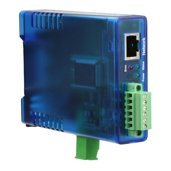
W&T IP-Watcher 2x2 Digital PoE 8 Appendix 8.1 LEDs In the following the meaning and function of the LEDs on the front panel of the IP-Watcher is explained 8.1.1 Power-LED Indicates presence of supply voltage. If the LED is not on, please check for correct wiring of the power supply. -
Page 74: Factory Defaults
W&T IP-Watcher 2x2 Digital PoE 8.2 Factory defaults Some situations require that the IP-Watcher be restored to its factory default settings. There are two ways to do this: . Using Web-Based Management . Using the Reset jumpers Restoring the factory default settings returns the unit to its state as shipped from the factory. -
Page 75: Alternative Ip Address Assignment
W&T IP-Watcher 2x2 Digital PoE Once the factory default settings have been restored, disconnect the unit from power, remove the jumper and close up the unit. Now proceed to startup. 8.3 Alternative IP address assignment The following describes methods for assigning an IP address to the unit instead of using the WuTility program. -
Page 76: Rarp Server (Unix Only)
W&T IP-Watcher 2x2 Digital PoE The IP address is now stored in non-volatile memory. This method can only be used if no IP address has yet been assigned to the IP-Watcher, i.e. the entry is 0.0.0.0. To change an already existing IP address, you must open the configuration menu from the browser or select the serial path. -
Page 77: Firmware Update Over The Network
W&T IP-Watcher 2x2 Digital PoE Before downloading, please write down the 5-digit model number found on the IP-Watcher. From our Web site you can get to the product overview sorted by article numbers, through which you can get directly to the data sheet for the device. Here you follow the link to the current version of the firmware. - Page 78 W&T IP-Watcher 2x2 Digital PoE Config >> Up/Download >> Download Config >> Up/Download >> Upload When downloading the device configuration, which is stored in XML format, you can download the IP-Watcher’s settings and make any necessary changes. The changed settings can then be loaded back into the device using the Upload function.
-
Page 79: Technical Data
W&T IP-Watcher 2x2 Digital PoE 8.6 Technical data Network Ethernet 10/100BaseT autosensing Protokol TCP- and UDP-Client, FTP, Mail, SNMP incl. Traps, Inventory, Groupmanagement Response times Data and switching traffic: typically 12ms Digital outputs 6 x digital out 6V-30V DC, 0.5A, max.
Need help?
Do you have a question about the IP-Watcher 2x2 Digital PoE and is the answer not in the manual?
Questions and answers