
Subscribe to Our Youtube Channel
Related Manuals for W&T Web-IO Digital 4.0


Summary of Contents for W&T Web-IO Digital 4.0
- Page 1 Manual Installation, Startup and Application Web-IO Digital 4.0 gvalid for: #57733 Web-IO 4.0 Digital 4xIn/Out #57736 Web-IO 4.0 Digital 16xIn/Out Release 1.51 October 2021...
- Page 2 © 10/2021 by Wiesemann und Theis GmbH Microsoft, MS-DOS, Windows, Winsock and Visual Basic are registered trademarks of the Microsoft Corporation. Subject to error and alteration: Since it is posssible that we make mistakes, you mustn’t use any of our statements without verification.
-
Page 3: Table Of Contents
Inhalt Content 1. Legal notices ..............5 Warning notice system ..................5 Qualified personnel .................... 5 Disposal ......................6 Symbols on the product ..................6 2. Safety notices ..............7 General notices ....................7 Intended use ....................... 7 Electrical safety ....................7 Batteries ...................... - Page 4 Inhalt Network connection ..................24 6. Initial start-up ..............25 Assigning the IP address ................. 25 Changing the set IP parameters ..............26 7. Basic settings ..............27 Configuring Inputs and Outputs ............... 27 Date / Time ....................... 28 Language / Info ....................28 Password ......................
-
Page 5: Legal Notices
Rechtliche Hinweise 1. Legal notices Warning notice system This manual contains notices that must be observed for your personal safety as well as to prevent damage to equipment. The notices are emphasized using a war- ning sign. Depending on the hazard level the warning notices are shown in decrea- sing severity as follows. -
Page 6: Disposal
Rechtliche Hinweise ly the safety and warning notices contained therein. Qualified personnel are defined as those who are qualified by their training and experience to recognize risks when handling the described products and to avoid possible hazards. Disposal Electronic equipment may not be disposed of with normal waste, but rather must be brought to a proper electrical scrap processing facility. -
Page 7: Safety Notices
Sicherheitshinweise 2. Safety notices General notices This manual is intended for the installer of the Web-IOs described in the manual and must be read and understood before starting work. The devices are to be installed and put in operation only by qualified personnel. Intended use 1DANGER The Digital Web-IOs manufactured by Wiesemann &... -
Page 8: Batteries
10 years and must be replaced only by a battery of the same type. When using the Web-IO Digital 4.0 in a network environment with access to a time server, the battery is not essential for correct function of the device and can be removed. - Page 9 Sicherheitshinweise #57733 #57736 Use a pointed object to press on the latching hooks on the side of the housing and at the same time pull the bottom of the housing out of the top shell. Then remove the stack of PCBs downwards from the housing. The buffer battery for the clock module is located in a holder on the upper PCB.
- Page 10 Sicherheitshinweise Batteries and rechargeables must not be disposed of with normal waste, recycling of used batteries and rechargeables is required by law. Used batteries may contain harmful substances which can damage the environment or your health if not disposed of properly. Batteries also contain important raw materials such iron, zinc, manganese or nickel and are recycled.
-
Page 11: Quick Startup
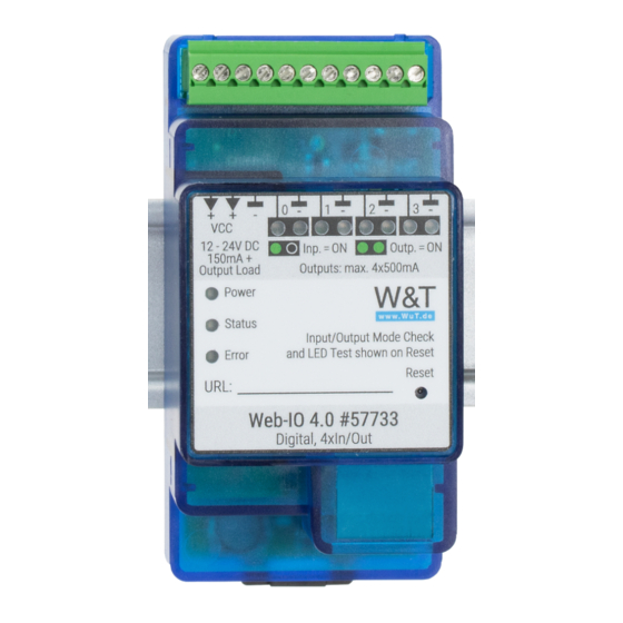
Schnellinbetriebnahme 3. Quick Startup Network connection Supply voltage #57733 #57736 12 - 24V 12 - 24V 12 - 24 V DC Inputs/Outputs 12 - 24V DC Inp. = ON Outp. = ON 150mA 150mA + 12-48V max. 4x500mA Out Output Load Outputs: max. -
Page 12: Product Introduction
Produktvorstellung 4. Product introduction Hardware The Web-IO devices differ in their mechanical design and hardware configuration: #57733 - Web-IO 4.0 Digital 4xIn/Out Network interface: RJ45 10/100BaseT / PoE Power: Screw terminal 12 … 24V DC Inputs/Outputs: 4 channels optionally as input or output Input switching threshold +9.5V (+/-1V) Output 12 ... -
Page 13: Network Security
Produktvorstellung Network security All available network services are configurable and must first be enabled by the administrator. By default only browser access, inventorying via Wutility, and the port for initializing firmware updates are enabled. DHCP is also enabled. You can explicitly specify for all communication paths whether the outputs may be accessible. -
Page 14: Application And Access Possibilities
Produktvorstellung Application and access possibilities Browser access Using password protected access, the status of inputs, counters and outputs can be monitored by browser access. You can also switch the outputs with the required access rights. It is also possible to upload a web page created entirely according to your own needs to the device. -
Page 15: Actions
Produktvorstellung Web-API - HTTP requests / AJAX The status of inputs, counters and outputs can be queried using HTTP requests. In addition the outputs can be directly controlled using HTTP requests. OPC DA / OPC UA Together with the W&T OPC Server the Web-IO can be accessed from any OPC client applications. -
Page 16: Installation And Wiring
Montage und Verdrahtung 5. Installation and wiring The described Web-IOs may be installed and wired by qualified personnel only. The generally applicable state of the art and corresponding prevailing regulations and standards must be observed. Montage #57733 The Web-IO 4.0 Digital 4xIn/Out is intended for installation in the control cabinet or sub-distribution. -
Page 17: Wiring #57733
Montage und Verdrahtung Terminal assignment 57733 Terminal Description / Function + Vcc - Device supply 12-24V 150mA@24V + Vcc - Device supply 12-24V 150mA@24V GND / Device supply Input 0 Switching threshold +8V / Output 0 24V max. 500mA GND - Output 0 Input 1 Switching threshold +8V / Output 1 24V max. - Page 18 Montage und Verdrahtung With a voltage supply of 24V, which is typical in industry, the Web IO draws approx. 100mA current. IO channels that are configured as outputs are also supplied via VDD. The loads to be switched must also be taken into account in the current consumption. Input wiring Each of the four IO channels has a plus and a minus terminal.
- Page 19 Montage und Verdrahtung Output wiring IO channels that are configured as outputs operate as current drivers and can be loaded with max. 500mA each. The positive voltage applied to VDD .is switched to the positive terminal of the IO channel, whereby the negative terminal is used as re- ference ground.
- Page 20 Montage und Verdrahtung Terminal assignment #57736 Klemme 1 Klemme 2 12 - 24 V DC 150mA + Output Load Power W&T Wiesemann &Theis GmbH In = ON Out = ON max. 16mA Porschestraße 12 Status 42279 Wuppertal max. Output Load 16 x 500mA In/Out Mode Check on Reset w w w.
- Page 21 Montage und Verdrahtung Terminal 2 Description / Function GND / Reference GND for Output GND / Reference GND for Output Input 5 Switching threshold +8V / Output 5 24V max. 500mA + Vdd - Auxiliary voltage 24V 2mA@24V for Input activation + Vdd - Auxiliary voltage 24V 2mA@24V for Input activation Input 6 Switching threshold +8V / Output 6 24V max.
-
Page 22: Wiring #57736
Montage und Verdrahtung Wiring #57736 Connection of the supply voltage V The Web IO is supplied with a DC voltage between 12 and 24V. 12 - 24V 12 1 12 - 24 V DC 150mA + Output Load Power W&T Wiesemann &Theis GmbH In = ON Out = ON... - Page 23 Montage und Verdrahtung Input wiring Each of the 16 IO channels has a plus and a minus terminal. The signal input for IO channels that are operated as inputs is on the respective plus terminal. When using potential-free contacts, we recommend switching the auxiliary voltage VDD-Out via the contact on the plus terminal.
-
Page 24: Network Connection
Montage und Verdrahtung Output wiring IO channels that are configured as outputs operate as current drivers and can be loaded with max. 500mA each. The positive voltage applied to VDD .is switched to the positive terminal of the IO channel, whereby the negative terminal is used as re- ference ground.. -
Page 25: Initial Start-Up
Inbetriebnahme 6. Initial start-up After the Web-IO has been properly installed and wired, the power supply can be switched on. All three status LEDs should light up briefly. After approx. 5 seconds only the Power LED should remain on. The Status LED may flash. If a valid signal is detected on one of the inputs, the corresponding LED also lights up. -
Page 26: Changing The Set Ip Parameters
Inbetriebnahme suggests the network parameters (subnet mask, gateway, DNS server) that also apply to the PC. If you want the Web-IO to work in the same subnet as the PC, you only need to adjust the IP address. If you select Address range > any network, you can also enter parameters which are different from your local network, for example to pre-configure the Web-IO for a different network. -
Page 27: Basic Settings
Grundeinstellungen 7. Basic settings The further configuration of the Web-IO is done using a web browser. Enter the IP address of the Web IO in the browser command line. In the navigation tree, click Login and choose Administrator as user. By default, no password is assigned and a click on the login button is sufficient to configure the Web-IO with administrator rights. -
Page 28: Date / Time
Grundeinstellungen Pulse mode By activating the Pulse Mode, the output automatically returns to the OFF state after the selected pulse duration when it is switched to the ON state. When switched on again during the pulse, the pulse duration starts counting again. Reset Allowed specifies that the output may also be switched to the OFF state during a current pulse. -
Page 29: Certificates
Basisanwendungen Certificates Protocols such as HTTPS or OPC UA are based on the TLS protocol. The encryption of the communication and the authentication of the communication partners is rea- lized via certificates. The Web IO identifies itself ex works with a self-signed certificate. Many applica- tions consider such certificates to be a security risk. -
Page 30: Basic Applications
Basisanwendungen 8. Basic applications The Web-IO has a wide range of different communication channels and supports various standard protocols. We recommend that you only enable the communication channels that are actually required for your application. This limits the possibility of unauthorized access and manipulation. First of all, we would like to introduce the three most frequently used communication channels: Browser access... - Page 31 Basisanwendungen Home The Home page provides an overview of inputs, outputs and the configured actions. With the appropriate login, the outputs can be switched and the counter can be deleted. Both must first be enabled under Web sites » Home. By default this is disabled.
-
Page 32: Sending Email
Basisanwendungen Sending email A few basic settings are necessary in order to send email messages. Network parameters If you want to send via a mail server on the Internet, it is important that the basic network settings are correct. Check under Basic settings » Network especially whether Gateway and DNS server are specified correctly. -
Page 33: Box-To-Box
Integration in bestehende Systeme Placeholder Description <dn> Device Name <inx> Name of the input No. x <onx> Name of the output No. x <t> Time stamp with date and time <$y> Year in format „YYYY“ <$m> Month in format „MM“ <$d>... -
Page 34: Integration Into Existing Systems
Integration in bestehende Systeme 9. Integration into existing systems The Web-IO supports some common standards and protocols and can be easily in- tegrated into many installed systems. MQTT After enabling MQTT and configuring in the menu branch Communication paths » MQTT the Web-IO supports two basic possibilities: 1. - Page 35 Integration in bestehende Systeme you determine in which state the output is to be switched or whether the state is to change. Example: A device writes the keyword ON as a topic in the path wut/webio123/set0 of the broker specified in the Web IO. This path and topic are specified as an initiator under MQTT subscribe for the Web IO.
-
Page 36: Rest
Integration in bestehende Systeme set for switching an output or deleting a counter. Possible functions are input, counter or output Via the IO number, starting at 0, the IO is specified. Publish IO states Example of the pulse of a state change at input 1: wut-0a4711/get/input/1 Depending on the state, the payload will be ON or OFF. - Page 37 Integration in bestehende Systeme Read access For read access REST uses the HTTP command GET. The Web IO supports three formats for responses to REST requests: • JSON • • Text The format used for replies can be determined using the request. Using http://<ip-adresse>/rest/json for example opens the entire process image of the Web-IO in JSON format.
- Page 38 Integration in bestehende Systeme “number” : 1, “state” : 0 “system” : “time” : “time” : “2016 - 09 - 09, 09 : 42 : 54” “diagnosis” : [ “time” : “06.09.2016 09 : 42 : 54”, “msg” : “Gerätestatus : OK” “diagarchive”...
- Page 39 Integration in bestehende Systeme “iostate” : “input” : [ “number” : 0, “state” : 0 Changing access POST is used for accesses that change the switching state of the outputs or delete the counters. For example to set the output to ON, a POST is sent to the following URL: http://<ip-adresse>/rest/json/iostate/output/1 The following parameters are sent as payload: Set=ON...
-
Page 40: Opc Da
Integration in bestehende Systeme The Web-IO responds: “iostate” : “counter” : [ “number” : 1, “state” : 0 To receive the responses in one of the other formats, simply replace the keyword json with xml or text. A detailed description of the supported REST requests and the structure of the replies can be found in the Web-IO Programming Manual (download at http://WuT.de.). -
Page 41: Opc Ua
Integration in bestehende Systeme OPC UA In addition to the classic OPC access via the W&T OPC server, the Web IO can also be addressed directly via OPC UA. The device provides OPC UA via a binary TCP protocol. The preset port of the server service corresponds to the standard port for this appli- cation: 4840. - Page 42 Integration in bestehende Systeme The device provides you with the OPC UA tree shown in the following (here at the example of the Web-IO #57737). Here are the most important variables that can be used to retrieve the states of the IO end points: •...
-
Page 43: Snmp
Integration in bestehende Systeme SNMP Both the IOs and the configuration of the Web-IO can be accessed via SNMP. The assignment between parameters and values and the object identifiers (OID) is stored in the private MIB. The private MIB can be downloaded directly from the Web- IO under Communication Channels »... -
Page 44: Modbus-Tcp
Integration in bestehende Systeme Access to inputs and outputs Reading the inputs, counters and outputs is always possible using GET requests to the corresponding OID. In the OID section wtWebioEA….InOut there are corresponding tables for this. The MIB is symmetrically structured for the various Web-IO models. Input and output tables are kept, which have a different number of entries depending on the Web-IO type. - Page 45 Integration in bestehende Systeme Modbus-Memory Bit range: addresse description memory length read bits read reg. Write bits write reg. (hexadec.) type (byte) with FC with FC with FC with FC 1000 Input 0 0x01, 0x02 1001 Input 1 0x01, 0x02 1002 Input 2 0x01, 0x02...
- Page 46 Aktionen 16- and 32-bit range: addresse description memory length read bits read reg. Write bits write reg. (hexadec.) type (byte) with FC with FC with FC with FC 2000 Inputs 0 - 11 16-bit 0x03, 0x04 2002 Outputs 0 - 11 16-bit 0x03, 0x04 2004...
-
Page 47: Actions
Aktionen 10. Actions The Action principle allows the Web-IO to issue individual alarms and messages – but also to switch the outputs. This is done based on defined IO states or other events. Up to 12 actions can be created and managed, whereby an individual name can be defined for each action. - Page 48 Aktionen Valid characters: represents all valid values in the respective input field (e.g. every minute or every hour) specifies a range of from…to (e.g. weekday “2-4” stands for Tuesday to Thursday, whereas entering “*” triggers the timer on all weekdays). Interval within the specified range (e.g.
-
Page 49: Actions
Aktionen Actions For actions which allow sending alarms, messages and other texts, placeholders can be used within the text which replace actual contents such as IO states, time etc. when performing an action. Placeholder Description <ix> State of the inputs No. x (ON/OFF) <ox>... - Page 50 Aktionen To send e-mail messages, access to the mail server must be configured and mail must be activated as a communication channel. All necessary settings can be made under Communication paths » Mail. In the info area you will find the general access data for the most common email providers.
- Page 51 Aktionen TCP messages When sending TCP messages the Web-IO operates as a TCP client. When initiating the action it opens a TCP connection to the specified TCP server address on the specified port, transmits the message or clear text, and then immediately closes the connection.
- Page 52 Zugriff aus eigenen Anwendungen Switching the own outputs The outputs can be switched to ON or OFF. Another possibility is to toggle the exist- ing state. Alternatively, several outputs can be switched simultaneously. For each selected output, you can specify whether it is to be set to ON or OFF. Switching the outputs of another Web-IO Also in this case, either one specific output or several outputs can be switched.
-
Page 53: Access From Own Applications
Zugriff aus eigenen Anwendungen 11. Access from own applications In addition to the numerous standardized access possibilities, the Web-IO also offers the option of accessing from your own application. This can be done via TCP/IP sockets from the common high-level languages. However, it is also possible to use common web techniques such as AJAX or PHP to communicate with the web IO. - Page 54 Zugriff aus eigenen Anwendungen The inputs are usually read using a polling procedure. Event-controlled processing is only possible after corresponding configuration of the input triggers. UDP peer To access the Web-IO via UDP using ASCII sockets, enable UDP ASCII-Sockets un- der Communication paths »...
- Page 55 Anhang paths » Web-API. A detailed description of the supported HTTP requests and more details about access using Web techniques such as AJAX and PHP can be found in the Web-IO programming manual (download at http://www.WuT.de). Follow the nanual link on the data sheet page of your Web-IO.
-
Page 56: Appendix
Anhang 12. Appendix Alternatives for IP address assignment In case IP addresses cannot be assigned using DHCP or the Wutility Tool, the Web IO offers two further options: Assigning the IP address using the ARP command This method can be used when the Web-IO does not yet have an IP address and the entry is 0.0.0.0. -
Page 57: Firmware Update
Anhang be made conveniently using web-based Management. Assigning the IP address through the serial port Only #57730 and #57734. • connect the Web-IO to a serial port of your computer. For a standard PC, an RS232 crossover cable is required. •... -
Page 58: Emergency Access
Technische Daten The current firmware for your Web-IO can be found on the respective Web data sheet page at www.WuT.de/article number, e.g. www.wut.de/57730 To install the firmware update, you need a Windows PC with the WuTility tool installed (included in the firmware archive) and unrestricted network access to the Web-IO. -
Page 59: Technical Data
Technische Daten 12. Technical data #57733 Connections, displays and control elements: Digital IOs: 4 channels selectable input/output operation As output: 12-24V DC / 500mA per channel Total fuse protection for all outputs 3A As input: max. 30V DC Switching threshold 9.5V +/- 1V „On“... - Page 60 #57736 Connections, displays and control elements: Digital IOs: 16 channels selectable input/output operation As output: 12-24V DC / 500mA per channel Total fuse protection for all outputs 3A As input: max. 30V DC Switching threshold 9.5V +/- 1V „On“ current = 2.2 mA Integrated 32-bit pulse counter Network: 10/100BaseT autosensing...
Need help?
Do you have a question about the Web-IO Digital 4.0 and is the answer not in the manual?
Questions and answers