Table of Contents
Advertisement
Synergy
User's Guide
The Arthrex Synergy
RF™
information for all components of the Arthrex Synergy
(Model AR-9800), including accessories. All operating personnel
must read this User's Guide thoroughly prior to using this system
and follow all safety warnings, cautions, and notes.
Arthrex, Inc.
1370 Creekside Blvd.
Naples, FL 34108-1945 USA
Toll Free: 1-(800) 934-4404
www.arthrex.com
Arthrex GmbH
Erwin-Hielscher-Strasse 9
81249 München, Germany
Tel: +49 89 909005-0
Fax: +49 89 909005-280
www.arthrex.de
DFU-0221-6 Revision 0 08/2020
© 2020 Arthrex, Inc. All rights reserved.
RF™
User's Guide provides safety operation
console
RF™
Advertisement
Table of Contents

Related Manuals for Arthrex Synergy AR-9800


Summary of Contents for Arthrex Synergy AR-9800
- Page 1 RF™ User’s Guide The Arthrex Synergy User’s Guide provides safety operation RF™ information for all components of the Arthrex Synergy console RF™ (Model AR-9800), including accessories. All operating personnel must read this User’s Guide thoroughly prior to using this system and follow all safety warnings, cautions, and notes.
- Page 2 This page intentionally left blank...
-
Page 3: Table Of Contents
Electromagnetic Compatibility ..................30 Basic Setup Procedure for the AR-9800 Console ............... 31 Setting up a Footswitch ..................... 32 Setting up the Arthrex Single Use, disposable Apollo RF® device (Probe) ......32 5.0 OPERATION AND FREQUENTLY USED FUNCTIONS ....... 34 Main Screen ........................ - Page 4 Footswitch Override Screen ....................42 Footswitches ........................44 5.3.1 Synergy Footswitch – Ablate Power Change button ............ 44 Accessory Arthrex Apollo RF® devices (Probe) ..............45 Normal Operation ......................46 System Shutdown ......................46 6.0 CLEANING AND DISINFECTING ..............47 Console AR-9800 ........................
- Page 5 List of Figures Figure 1 Connection Diagram ......................15 Figure 2 Front Panel of Console ......................17 Figure 3 Rear Panel of Console ......................18 Figure 4 Error Screen Display ......................20 Figure 5 Main Screen Display ......................34 Figure 6 Settings Menu Display - Operation ...................
- Page 6 List of Tables Table 1 Connection Elements ......................15 Table 2 Front Panel Elements ......................17 Table 3 Rear Panel Elements ......................18 Table 4 AR-9800 Display Messages ....................19 Table 5 Error Screen Display – Descriptions .................. 20 Table 6 AR-9800 Console Specifications ..................
- Page 7 This is not a warranty document. For all warranty information, including disclaimers, exclusions, terms, conditions and related provisions, refer to the "Arthrex U.S. Product Warranty" section of the Arthrex, Inc. website, found at www.arthrex.com whose provisions are incorporated herein by reference.
-
Page 8: General Warnings, Training And Safety Notices - Read This First
(AR-9800) without resolving an alarm could result in a serious patient adverse event. 4. Failure to adhere to the set up instructions and use of Arthrex certified devices may result in inaccurate sensing and feedback by the device. It is imperative that the user is aware of the potential compromise in patient safety when an alarm on the console is ignored or silenced incorrectly. - Page 9 16. Biohazard waste, such as explanted devices, needles and contaminated surgical equipment, should be safely disposed of in accordance with the institutions policy. 17. Serious incidents should be reported to Arthrex Inc., or an in-country representative, and to the health authority where the incident occurred. DFU-0221-6r0_fmt_en-US...
- Page 10 8. This device has passed testing for EMI / RFI radiation and susceptibility and EMC compatibility. This device may cause interference to other devices in the near vicinity if not set up and used as Arthrex instructs. 9. Do not attach compatible disposable devices or footswitches during the Self Test or the Programming Modes.
- Page 11 (DFU-0242-XX) for detailed device cleaning and sterilization instructions included with each device Additional copies of this insert can be obtained from the Arthrex website at www.arthrex.com, or by contacting your local Arthrex Representative. NOTE: This identifies information and training that can simplify the setup and operation of this device.
- Page 12 General Warnings, Training and Safety Notices - Read This First Synergy User’s Guide RF™ video, and electronic formats. The Arthrex website also provides detailed surgical technique information and demonstrations. Or, contact your Arthrex representative for an onsite demonstration. DFU-0221-6r0_fmt_en-US Page 10 of 58...
-
Page 13: Symbol Definitions
User’s Guide RF™ Symbol Definitions All of the symbols used on the labeling along with the title, description and standard designation number may be found on our website at www.arthrex.com/symbolsglossary. Caution: Federal law Safety Sign restricts this device to Follow operating... - Page 14 Electrical Waste electromagnetic radiation Footswitch connection Quantity Universal Serial Bus Serial port 10101 [For use ONLY with [Arthrex integration] thumb drive] Serial number Non Sterile RF probe handpiece Catalog number International Protection Do not use if package marking is damaged Square brackets that enclose a letter, number or lower-case Roman numeral reference a callout on a line drawing.
-
Page 15: Shipping, And Unpacking Information
Business. The warranty is not valid if modifications are made to the product or repairs are completed outside of Arthrex or an authorized Arthrex distributor. Arthrex will answer any questions referring to the quality, reliability and/or shelf life of any product identified in this User’s Guide. -
Page 16: Product Description And Intended Use
User’s Guide RF™ 2.0 Product Description and Intended Use Product Description The Arthrex Synergy Generator is classified as a FDA Class II medical device. The Arthrex Synergy Generator is an advanced electrosurgical generator utilizing feedback from the surgical site such as, voltage, current and power. It is designed to meet the needs of arthroscopic surgical procedures. -
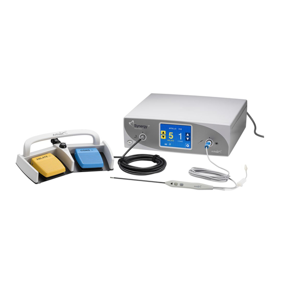
Page 17: Figure 1 Connection Diagram
Product Description and Intended Use Synergy User’s Guide RF™ Figure 1 Connection Diagram Table 1 Connection Elements 1. Generator/Console 2. Power Cord 3. Footswitch 4. Footswitch Cable Connector 5. RF Ablation Device (Probe) 6. Probe Cable Connector 7. Suction Tube Connector Save the packaging for later transport of the device. -
Page 18: Indications For Use And Contraindications
Synergy User’s Guide RF™ 2.1.1 Indications for Use and Contraindications Indications for Use The Arthrex Synergy System, when used with an Apollo Ablation Device RF® (Probe), is intended for use as a complete system in the resection, ablation, and coagulation of soft tissue and hemostasis of blood vessels in arthroscopic and orthopedic procedures. -
Page 19: Product Features
Product Description and Intended Use Synergy User’s Guide RF™ Product Features 2.2.2 AR-9800 Console - Front View Figure 2 shows the front panel of the AR-9800 console. The features and symbols are identified in Table 2 below. Figure 2 Front Panel of Console Table 2 Front Panel Elements 1. -
Page 20: Ar-9800 Console - Rear View
2. Equipotential Bonding Pin with Stamped Equipotential Bonding Symbol 3. Address label 4. Fan 5. USB port (For use ONLY by service technicians) 6. Serial ports for Arthrex integration (to only be connected to IEC 60601-1 approved equipment) 7. Serial number label 8. Model number label 9. -
Page 21: Ar-9800 Display Messages
The console's Touch Screen Display [5] provides information about the status of the AR-9800 settings in real time. A list of informational and error messages is shown in Table 4 below. Messages shaded in gray denote that Arthrex technical support should be contacted for further instructions. Error display messages reported to Arthrex technical services should include the Error Message and Error Code for reference (See Figure 4). -
Page 22: Figure 4 Error Screen Display
Power supply self-check failure, contact Arthrex technical services. "RF Output Failure" Power supply self-check failure, contact Arthrex technical services. "Touchscreen Circuit Failure" Touch panel failure, contact Arthrex technical services. Figure 4 Error Screen Display Table 5 Error Screen Display – Descriptions 1. -
Page 23: Technical Specifications
Technical Specifications Synergy User’s Guide RF™ 3.0 Technical Specifications Console Table 6 AR-9800 Console Specifications Width 40.64 cm (16.00 inches) Height 13.335 cm (5.250 inches) Depth 37.338cm (14.7 inches) Weight 6.8 kg (15 lbs.) Water protection IP22 Mains cable 10 A/250 V Power entry module IEC 320/C13 Fuse value... -
Page 24: Safety, Emc, And Regulatory Requirements
Technical Specifications Synergy User’s Guide RF™ Safety, EMC, and Regulatory Requirements Table 10 Safety, EMC, and Regulatory Requirements Parameter Parameter Value Class I IEC 60601-1 (protection against electric shock) FDA Class Class II System Classification EU Class Class IIb Health Canada Class Class 3 Domestic Certification ES60601-1:2005/A1:2012... -
Page 25: Power Curves
Technical Specifications Synergy User’s Guide RF™ Power Curves DFU-0221-6r0_fmt_en-US Page 23 of 58... - Page 26 Technical Specifications Synergy User’s Guide RF™ DFU-0221-6r0_fmt_en-US Page 24 of 58...
- Page 27 Technical Specifications Synergy User’s Guide RF™ DFU-0221-6r0_fmt_en-US Page 25 of 58...
- Page 28 Technical Specifications Synergy User’s Guide RF™ DFU-0221-6r0_fmt_en-US Page 26 of 58...
- Page 29 Technical Specifications Synergy User’s Guide RF™ DFU-0221-6r0_fmt_en-US Page 27 of 58...
- Page 30 Technical Specifications Synergy User’s Guide RF™ DFU-0221-6r0_fmt_en-US Page 28 of 58...
-
Page 31: Setup
AC mains outlet. Please use the appropriate plug and a reliable ground conductor. Arthrex supplies separate power cords for the U.S. and Europe with the AR- 9800. Contact your Arthrex representative if you need a power cord that must meet the electrical standards of another country. -
Page 32: Replacing The Fuses
EMC compatibility. This device may cause interference to other devices in the near vicinity if not set up and used as Arthrex instructs. AR-9800 has been designed to accept EMC from other devices within the limitations as described in Section 13.0. -
Page 33: Basic Setup Procedure For The Ar-9800 Console
Inspect all cords for cracks, nicks and breaks. Inspect all connectors for damaged or missing parts. 1. Place the AR-9800 on a flat, dry surface, such as the AR-6481 Arthrex Arthroscopy cart. 2. Connect the receiver end of the power cord for the AR-9800 into the AC Supply main input socket and the plug end to the facility AC mains supply. -
Page 34: Setting Up A Footswitch
W A R N I N G ! Use only Arthrex approved accessories. Other accessories may result in increased emissions or decreased immunity of the system. Contact your Arthrex representative for a complete list of accessories. DO NOT modify any accessory. - Page 35 Wrapping cables around metal objects may induce currents that could lead to shock, fire or injury to patient or surgical personnel. Only use Arthrex RF devices (Probes) that have been developed by Arthrex specifically for the Synergy console.
-
Page 36: Operation And Frequently Used Functions
User’s Guide RF™ 5.0 Operation and Frequently Used Functions Users of this device should contact their Arthrex representative if they require a more comprehensive surgical technique. W A R N I N G ! The safety and effectiveness of the AR-9800 is verified and documented;... - Page 37 Operation and Frequently Used Functions Synergy User’s Guide RF™ Change button on the Synergy Footswitch (see Figure 12) or Apollo probe (see Figure 13) can RF® also adjust the Ablate Power setting. Each activation of the Ablate Power Change button increases the Ablate Power setting by 1 unit, in a positive direction only.
-
Page 38: Settings Menu Main Screen
Operation and Frequently Used Functions Synergy User’s Guide RF™ Settings Menu Main Screen The Settings Menu provides access to settings and information screens. There are seven buttons described in Table 12 below. Settings Menu Display - Operation Figure 6 Settings Menu Display - Operation Table 12 1. - Page 39 Operation and Frequently Used Functions Synergy User’s Guide RF™ 6. Home button When the Home button is pressed, the software displays the Main screen, section 5.1 above. 7. Info Button When the Info Button is pressed, the software displays the Information screen, see section 5.2.2 below.
-
Page 40: Language Selection Screen
Operation and Frequently Used Functions Synergy User’s Guide RF™ Language Selection Screen 5.2.1 The Language Selection screen displays a list of available languages with radio buttons. The software supports the following languages: English, German, French, Italian and Spanish. It also includes three navigation buttons: Menu, Home and Cancel as described in Table 13 below. -
Page 41: Reset Defaults Screen
Returns to the main screen. 5.2.2.1 Arthrex Apollo RF® device (Probe) Limits - IDR The Arthrex Synergy generator has built in intelligent device recognition (IDR) for Arthrex Apollo probes. When attached, the recommended setting will be RF® automatically applied, but individuals that desire an alternate setting can use the ABLATE power, COAG power, or Ablate power change button (see Figure 13) on the device to change the settings. -
Page 42: Figure 9 Reset Defaults Screen - Operation
Operation and Frequently Used Functions Synergy User’s Guide RF™ Figure 9 Reset Defaults Screen - Operation The software displays two buttons that allows the user to confirm resetting of factory defaults as described in Table 15 below. The defaults that are reset include: Language, Footswitch Override, Volume, probe ablation and coag settings. -
Page 43: Probe Buttons
Operation and Frequently Used Functions Synergy User’s Guide RF™ Probe Buttons 5.2.4 The Probe Buttons screen has radio buttons to enable or disable the ablate power change button on the Apollo probe handpiece (See Figure 13). RF® At the End User’s discretion, the ablate power change button on the probe handpiece can be disabled to prevent inadvertent activation while using the hand controls. -
Page 44: Footswitch Override Screen
(Probe) hand controls are active. Care must be taken not to activate the device inadvertently. In the default mode, the buttons on the hand-control of the Arthrex Apollo RF® probe will not function when a footswitch is attached to the console. The End... -
Page 45: Figure 11 Footswitch Override Selection Screen - Operation
Operation and Frequently Used Functions Synergy User’s Guide RF™ the Apollo probe and the footswitch will both operate the probe. This screen RF® also includes Menu, Home and Cancel buttons as described in Table 17 below. Footswitch Override Selection Screen - Operation Figure 11 Table 17 Footswitch Override Display - Operation... -
Page 46: Footswitches
Operation and Frequently Used Functions Synergy User’s Guide RF™ Footswitches The footswitch cable connects and locks to the console to prevent accidental separation during use. To avoid damage, always disconnect the footswitch by pulling on the cable connector shell (plug) only. Figure 12 Synergy Footswitch - Description... -
Page 47: Accessory Arthrex Apollo Rf® Devices (Probe)
The COAG button will activate the COAG function as long as the button is depressed. If two buttons are depressed, the button that was depressed first will take precedence and the second button to be depressed will be ignored. Accessory Arthrex Apollo devices (Probe) RF®... -
Page 48: Normal Operation
Operation and Frequently Used Functions Synergy User’s Guide RF™ Normal Operation Normal operation mode for Ablation and Coag is 10 seconds on, 30 seconds off. System Shutdown 1. Turn the power switch to the off position on the console. 2. Disconnect the power cord from the wall outlet. 3. -
Page 49: Cleaning And Disinfecting
Cleaning and Disinfecting Synergy User’s Guide RF™ 6.0 Cleaning and Disinfecting Console AR-9800 The AR-9800 console is provided non-sterile and should not be sterilized. The AR-9800 console can be cleaned/disinfected using a cloth and commercially available surfactants or surface disinfectants only. The AR- 9800 must not be submersed in any liquid. -
Page 50: Sterilization
RF® disposable devices (DFU-0242-XX) cleaning and sterilization instructions included with each device. Additional copies of this insert can be obtained from the Arthrex website at www.arthrex.com, or by contacting your local Arthrex Representative. Transmissible Spongiform Encephalopathy Agents It is outside the scope of this document to describe in detail the precautions that should be taken for Transmissible Spongiform Encephalopathy (TSE) Agents. -
Page 51: Maintenance
If it becomes necessary to return the console or accessory devices to Arthrex for service, please clean them before shipping. If fluid or particles splash on the display, clean with a micro-fiber cloth by gently wiping in a circular motion. -
Page 52: Technical Support
RF™ 9.0 Technical Support For assistance in using the products identified in this User’s Guide, contact an Arthrex representative or call the Arthrex Technical Support Hotline at 1-(888) 420-9393, Monday through Friday from 9:00 AM to 5:00 PM EST; at +49 89 909005 8800 or techsupport@arthrex.de from 8:00 AM to 5:00 PM CET. -
Page 53: Troubleshooting
2. Call Arthrex Service. If the problems persist, disinfect the Synergy System and send in to Arthrex using the original packaging. Always send the corresponding accessory device and if applicable, the footswitch together with the console. Please enclose a brief explanation of the malfunction. -
Page 54: Repair Policy
For more information about where you can drop off your medical electronic equipment at the end of its useful life for recycling, please contact Arthrex Customer Service Department. -
Page 55: Electromagnetic Emissions
Synergy User’s Guide RF™ 13.0 Electromagnetic Emissions Table 21 Guidance and Manufacturer’s Declaration – Electromagnetic Emissions The AR-9800 Synergy system is intended for use in the electromagnetic environment specified below. The customer or the user of the AR-9800 Synergy system should assure that it is used in such an environment. -
Page 56: Guidance And Manufacturer's Statement - Electromagnetic Immunity
Synergy User’s Guide RF™ Table 23 Guidance and Manufacturer's Statement - Electromagnetic Immunity The AR-9800 Synergy System is intended for use in the electromagnetic environment specified below. The customer or the user of the AR-9800 Synergy System should ensure that it is used in such an environment. - Page 57 Synergy User’s Guide RF™ Immunity test IEC 60601 test level Compliance level Electromagnetic environment - guidance Power 30 A/m 30 A/m @ 50 & 60 Hz Power frequency frequency magnetic fields should (50/60 Hz) be at levels magnetic field characteristic of a IEC 61000-4-8 typical location in a typical commercial or...
- Page 58 Synergy User’s Guide RF™ Table 23 (cont.) Guidance and Manufacturer's Statement - Electromagnetic Immunity The AR-9800 Synergy System is intended for use in the electromagnetic environment specified below. The customer or the user of the AR-9800 Synergy System should ensure that it is used in such an environment.
-
Page 59: Guidance And Manufacturer's Statement - Recommend Separation
Synergy User’s Guide RF™ Immunity IEC 60601 Compliance Electromagnetic environment - guidance test test level level exceeds the applicable RF compliance level above, the Model AR-9800 should be observed to verify normal operation. If abnormal performance is observed, additional measures may be necessary, such as re-orienting or relocating the Model AR-9800 b Over the frequency range 150 kHz to 80 MHz, field strengths should be less than 3 V/m. - Page 60 Synergy User’s Guide RF™ Naples, FL 34108-1945 USA Customer Service +1-(239) 643-5553 Arthrex, Inc. 1370 Creekside Blvd. Naples, FL 34108-1945 USA www.arthrex.com Customer Service 1-(800) 934-4404 Toll-Free Technical Support: 1-(888) 420-9393, Monday through Friday, 9:00 AM – 5:00 PM EST.
Need help?
Do you have a question about the Synergy AR-9800 and is the answer not in the manual?
Questions and answers