Table of Contents
Advertisement
AR-3200-0025
AR-3210-0018
AR-3210-0021
AR-3210-0022
AR-3210-0023
AR-3210-0025
AR-3210-0026
AR-3210-0028
AR-3210-0029
AR-3210-0030
AR-3210-0031
AR-3210-0032
AR-3210-0033
DFU-0332 Revision 0
06/2020
Synergy
Instructions for Use Manual
ID™
The Arthrex Synergy
Camera Head User's Guide provides important
information for the safe operation of all components of the
ID
Synergy
Camera System, including accessories. Read
this User's Guide thoroughly prior to using this system
and keep it in an easily accessible place for use by all
operating personnel. Read and follow all safety warnings,
cautions and precautions.
Arthrex, Inc.
1370 Creekside Blvd.
Naples, FL 34108, USA
+1 (800) 934-4404
www.arthrex.com
Technical Support
1-(800) 391-8599
ID ™
System
System Camera Control Unit and
EC
REP
Arthrex GmbH
Erwin-Hielscher-Strasse 9
81249 München, Germany
+49 89 909005-0
www.arthrex.de
Advertisement
Table of Contents

Related Manuals for Arthrex SynergyID AR-3200-0025


Summary of Contents for Arthrex SynergyID AR-3200-0025
- Page 1 Synergy ID ™ System Instructions for Use Manual ID™ The Arthrex Synergy System Camera Control Unit and Camera Head User’s Guide provides important information for the safe operation of all components of the Synergy Camera System, including accessories. Read this User’s Guide thoroughly prior to using this system and keep it in an easily accessible place for use by all operating personnel.
- Page 2 This is not a warranty document. For all warranty information, including disclaimers, exclusions, terms, conditions, and related provisions, refer to the “Arthrex U.S. Product Warranty” section of the Arthrex, Inc. website, found at www.arthrex.com whose provisions are incorporated herein by...
-
Page 3: Table Of Contents
Table of Contents Introduction ............................1 Intended Use ..........................1 Contraindications .......................... 1 Warnings and Precautions ......................1 Symbol Definitions ........................7 End of Life, Environmental Directives ................... 9 Initial Use of the Device ........................ 9 Unpacking and Inspecting the Device ..................10 Returning the Device ........................ - Page 4 List of Figures Front Panel [AR-3200-0025] ....................11 Figure 1- Synergy Rear Panel ..........................12 Figure 2- Synergy Figure 3- AR-3210-0023 4K SynergyUHD4 Camera Head, autoclavable ............13 Figure 4- AR-3210-0029 4K SynergyUHD4 Broadband Camera Head, autoclavable ........13 Figure 5-AR-3210-0018 HD, SynergyUHD4 Camera Head, autoclavable ............14 Figure 6-AR-3210-0031 4K Ultra SynergyUHD4 Camera Head, autoclavable ..........
-
Page 5: Introduction
Arthrex Synergy System tissue perfusion, and at least one of the major and accessories. The safe and effective use... - Page 6 Endoscopically Used Accessory, which are video system be for the Arthrex Synergy intended to be inserted into the patient, should maintained, sterilized, and ready to be be checked to ensure there are no unintended implemented.
- Page 7 used to minimize total Patient Leakage emission window which may cause Current. severe burns. 18. Applied Parts of other ME Equipment used • Surface temperatures of the insertion within the configuration for Endoscopic portion of the endoscope as well as light Application shall be type BF or CF Applied guide connectors on the Camera Parts.
- Page 8 Arthrex representative for an onsite appliance inlet module. demonstration. 8. This device may only be connected to 2. Only use the device with Arthrex compatible endoscopes which, in their intended use and equipment listed in Section 2.2. technical specifications, are appropriate for...
- Page 9 Notify your Arthrex Sales device. Representative. If it is necessary to return (b) Increase the separation between the the camera head to Arthrex for service, equipment. disinfect the camera head before shipping (c) Connect the equipment into an outlet on and reference “Returning the Device”.
- Page 10 19. In CE accepting Countries: Procedures 21. In CE accepting Countries: There are no carried out using these devices may be used on unacceptable residual risks or uncertainties the general population. associated with the clinical use of these devices. 20. In CE accepting Countries: The clinical benefits associated with the use of these devices outweigh the known clinical risks.
-
Page 11: Symbol Definitions
Symbol Definitions All of the symbols used on the labeling along with the title, description and standard designation number may be found on our website at www.arthrex.com/symbolsglossary. Safety Sign Caution: Federal Law Restricts Follow Operating this device to Instructions sale by or on the order of a Physician. - Page 12 Defibrillation Proof Keep Dry Type CF Equipment Pressure Limits for Storage and Alternating Current Transport Protective Earth Humidity Limits [Ground] for Storage and Transport Equipotential Universal Serial [Equipment Potential] WEEE [Waste Electronics and RF Symbol. Non- Electrical ionizing Equipment] Symbol. Electromagnetic Regarding European Radiation...
-
Page 13: End Of Life, Environmental Directives
Control Unit is intended to be used outside the Patient Vicinity. endoscopic video equipment at the end of its useful life for recycling, please contact Arthrex 6. Additional peripheral equipment Customer Service Department. connected as part of the Endoscopic... -
Page 14: Unpacking And Inspecting The Device
Unpacking and Inspecting the transport packaging. Please make sure that all Device required information has been supplied. Call Arthrex for an RMA Number for the device return for service. Upon receipt, carefully unpack the Synergy • Owner’s Name Camera Control Unit (CCU) and accessories. -
Page 15: System Indicators
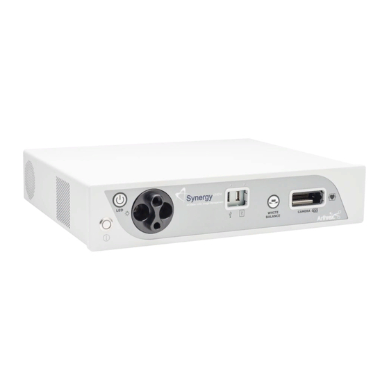
Figure 1- Synergy Front Panel [AR-3200-0025] 3. USB Port-Connect USB devices here. System Indicators 4. iPAD USB Port-Connect iPAD to this port. Synergy Front Panel 1.9.1 5. “WHITE BALANCE” Button-Press to initiate camera white balance. 1. On/Standby Switch-The On/Standby switch 6. - Page 16 3. Display Ports (2X)-Supplies UHD Video Signal output in either 1.1 [dual cable] or 1.2 13. Potential Equalization Connector (POAG)- [MST]. Potential Equalization Connector per DIN 42801. NOTE: Arthrex recommends connecting Synergy to the primary surgical monitor via NOTE: purpose Potential multiple output types (e.g., display port and...
-
Page 17: Figure 3- Ar-3210-0023 4K Synergyuhd4 Camera Head, Autoclavable
Figure 3- AR-3210-0023 4K SynergyUHD4 Camera Head, autoclavable Figure 4- AR-3210-0029 4K SynergyUHD4 Broadband Camera Head, autoclavable DFU-0332r0_fmt_en-US Page 13 of 64... -
Page 18: Figure 5-Ar-3210-0018 Hd, Synergyuhd4 Camera Head, Autoclavable
Figure 5-AR-3210-0018 HD, SynergyUHD4 Camera Head, autoclavable Figure 6-AR-3210-0031 4K Ultra SynergyUHD4 Camera Head, autoclavable DFU-0332r0_fmt_en-US Page 14 of 64... -
Page 19: Figure 7-Ar-3210-0033 4K Synergy
Figure 7-AR-3210-0033 4K Synergy 4MOS Camera Head, autoclavable 1.9.3 Camera Heads with Integrated Optics 1. Button 1-A programmable button that can activate various functions of the 3. Focus Ring-Used to sharpen, or bring camera. See “Optional Tablet Data Input into focus, the image detail. Device”... -
Page 20: Figure 8-Ar-3210-0025 4K Synergyuhd4 C-Mount Camera Head, Autoclavable, Ar-3210-0028 4K
Figure 8-AR-3210-0025 4K SynergyUHD4 C-Mount Camera Head, autoclavable, AR-3210-0028 4K SynergyUHD4 C-Mount w/20 foot cable, autoclavable and Not Pictured AR-3210-0026 4K SynergyUHD4 C-Mount Camera Head, 0 Degree, autoclavable Figure 9-AR-3210-0030 4K SynergyUHD4 C-Mount Broadband Camera Head, autoclavable DFU-0332r0_fmt_en-US Page 16 of 64... -
Page 21: Figure 10-Ar-3210-0021 Hd Synergyuhd4 C-Mount Camera Head, Autoclavable, And Not Pictured Ar-3210-0022 Hd Synergyuhd4 C-Mount Camera Head, 0 Degree, Autoclavable
Figure 10-AR-3210-0021 HD SynergyUHD4 C-Mount Camera Head, autoclavable, and Not Pictured AR-3210-0022 HD SynergyUHD4 C-Mount Camera Head, 0 Degree, autoclavable Figure 11-AR-3210-0032 4K Ultra SynergyUHD4 C-Mount Camera Head, autoclavable C-Mount Camera Heads 1.9.4 2. Button 2-A programmable button that can 1. -
Page 22: System Installation And Operation With Data Input Device
NOTE: If there is no Light Guide cable cables may be used instead of Display Port connected to the Synergy CCU, pressing cables.) Note: Arthrex recommends the On/Standby Switch will not activate the connecting Synergy to the primary surgical LED light engine until one is connected. -
Page 23: Figure 12- Synergy Typical Interconnect Diagram With Optional Digital Documentation Tablet
Figure 12- Synergy Typical Interconnect Diagram With OPTIONAL Digital Documentation Tablet [Integrated Optics Heads] DFU-0332r0_fmt_en-US Page 19 of 64... -
Page 24: Accessories For Intended Use
Part Number Description AR-3250-XXXX Arthrex Monitors SONY UP-PR80MD Medical Grade Printers SONY UP-PR80MD with UP- DR80MD/NKIT AR-3350-XXXX Arthrex Arthroscopes AR-3351-XXXX Arthrex Laparoscopes AR-3352-XXXX Arthrex Hi Mag Laparoscopes AR-3355-XXXX Arthrex C-Mount Arthroscopes AR-3200-1013 Synergy Documentation Tablet DFU-0332r0_fmt_en-US Page 20 of 64... - Page 25 AR-3200-1030, -1034, -1036, -1042, -1043, Synergy.net Licenses -1044, -1045, -1046, -1047, -1049 AR-3210-XXXX Arthrex C-mount couplers AR-3200-1010, -1012 Arthrex encrypted USB sticks AR-3200-1040 Arthrex Synergy System Integration Cable Kit AR-3370-0006 Arthrex Starfish AR-3370-0008 Arthrex C-Mount Starfish AR-3200-1018 Synergy Laser Light Source AR-3201-1005...
-
Page 26: System Setup Facility And Surgeon Settings
System Setup Facility and Surgeon Settings NOTE: Facility, surgeon, and procedural settings are made from the Synergy ’s Tablet Data Input Device. Screens may appear slightly different than those shown in this document depending on the particular features enabled on Synergy Figure 14-System Maintenance System Set-Up can be accessed by pressing the Maintenance Icon 2.3.1... -
Page 27: Figure 15-System Maintenance Screen
Figure 15-System Maintenance Screen 2.3.2 Selecting “System” enables several facility preferences to be setup; • User can input the facility name associated with that specific Synergy • User can select the language used with Synergy • User can select number of cases saved to system before data is automatically purged. •... -
Page 28: Figure 16-Date & Time Screen
Figure 16-Date & Time Screen 2.3.3 Selecting “Date & Time” enables adjustment of the Synergy date and time settings. • User can use a network time server or user can select the date and time options manually. DFU-0332r0_fmt_en-US Page 24 of 64... -
Page 29: Figure 17-Print Settings Screen
Figure 17-Print Settings Screen 2.3.4 Selecting “Print Settings” enables adjustment of the Synergy print settings. • User can enable the use of a local printer and select the paper size for that printer. DFU-0332r0_fmt_en-US Page 25 of 64... -
Page 30: Figure 18-System Maintenance Network
Figure 18-System Maintenance Network 2.3.5 Selecting “Network” allows for connecting the Synergy system to a facility network. Fields are: • Host Name • Show Network Status • IP Address • Subnet Mask • Default Gateway • Primary DNS • Enable Wi-Fi •... -
Page 31: Figure 19-Surgeon Management List
Figure 19-Surgeon Management List 2.3.6 Surgeons can be added to the Synergy with their own system preferences. 2.3.7 To add surgeons and their preferences, press the maintenance icon on the Synergy Tablet Data Input Device and then select Surgeon Management. A list of surgeons will appear. -
Page 32: Figure 21-Surgeon Preferences Settings
Figure 21-Surgeon Preferences Settings 2.3.9 Surgeon preferences can be defined for the following: • Camera Buttons • NIR Camera Buttons • Printer Settings • Print Settings • Multimedia • Web Server Access • Display • DICOM • Augmented Reality There are two sets of camera button settings. One set is specific for 4MOS camera heads and the other set applies to all other camera head connected to the CCU. -
Page 33: Figure 22-Surgeon Management Procedures Select
Figure 22-Surgeon Management Procedures Select 2.3.10 Procedure preferences can be added to individual surgeon preferences. On the surgeon management list, select a surgeon, and a list of procedures will appear 2.3.11 Select the appropriate Procedure for the Surgeon. If the procedure is not currently in the list, select the “Create New Procedure”... -
Page 34: Figure 23-Surgeon Procedure Settings
Figure 23-Surgeon Procedure Settings Once a Procedure has been added select the “Procedure Settings” next to the Procedure 2.3.12 name to configure camera, pump, and shaver settings associated with the Procedure. DFU-0332r0_fmt_en-US Page 30 of 64... -
Page 35: Icon Guide
Icon Guide 2.4.1 Figure 24 shows what is displayed on a surgical monitor when a Synergy is first powered on. Figure 24-Connectivity Icons 2.4.2 In the lower left corner of the screen are icons that represent connectivity with Synergy . The icons shown below represent tablet, network, and Synergy.net connectivity. - Page 36 2.4.4 Beneath each of the icons is a status bar. The color of the bar indicates the status of the connection. A status bar that is green means that there is active connectivity between that device and Synergy and no issues are detected. A status bar that is blue means that there is active connectivity between that device and Synergy , no issues are detected, and an active data transfer is taking place (e.g., images are exporting to a USB device or a DICOM export is...
-
Page 37: Scheduling And Starting Cases
Scheduling and Starting Cases Figure 25-Scheduling a case To schedule a case, press the “+ Add New Case” icon 2.5.1 DFU-0332r0_fmt_en-US Page 33 of 64... -
Page 38: Figure 26-Scheduling A Case
Figure 26-Scheduling a Case 2.5.2 Select the “Room” (if present, optional field depending on how system is configured), “Surgeon” and/or “Procedure,” and enter data in the following required fields. • Patient First Name • Patient Last Name Patient I.D. # •... -
Page 39: Figure 27-Starting A Case
Figure 27-Starting a Case 2.5.5 To start a case, select the case/patient from the Case List and press the “Start” icon. NOTE: Cases may also be started from the “Add Case” screen by entering the required fields and pressing the “Start” icon. DFU-0332r0_fmt_en-US Page 35 of 64... -
Page 40: Figure 28-Confirming A Case
Figure 28-Confirming a Case 2.5.6 A “Case Confirmation” window will appear showing the patient and case demographics. If the information is correct press the “Start” icon. DFU-0332r0_fmt_en-US Page 36 of 64... -
Page 41: Figure 29-Camera Settings Change During Case
• System Capture Settings • Print Settings • Arthrex Resection Integration Settings • Arthrex RF Integration Settings • Arthrex Fluid Management Integration Settings • Arthrex Insufflation Integration Settings • Augmented Reality Settings • NIR Settings DFU-0332r0_fmt_en-US Page 37 of 64... -
Page 42: Figure 30-Ending A Case
Figure 30-Ending a Case 2.5.8 Ending a Case; to end a case, press the “End Case” Icon. NOTE: An “End the Case?” confirmation message will appear. If confirmed, the case will end and the Synergy Tablet Data Input Device will transition to the case review screen. DFU-0332r0_fmt_en-US Page 38 of 64... -
Page 43: Status Notification Icons
Status Notification Icons Figure 31-Status Notification Icons 2.6.1 When a manual export/print is performed, the status notification for the action will appear on the tablet. The blue progression bar will indicate that the export is in progress. Once the export is complete the status bar will turn green. -
Page 44: Figure 32-Export Status
Figure 32-Export Status 2.6.2 The system in Figure 33 displays a successful USB export and an iPad export in progress. DFU-0332r0_fmt_en-US Page 40 of 64... -
Page 45: Figure 33-Export And Print Status During A Case
Figure 33-Export and Print Status During a Case 2.6.3 Export and print statuses will also display during surgery if auto export or auto print is enabled for the surgeon using the system. A successful export will display a green checkmark for the images completed. -
Page 46: System Operation Without Tablet Data Input Device
2. The camera will take approximately 60 System Operation without Tablet seconds to fully load its boot software. When Data Input Device the software has fully loaded, you will see the Synergy Initial Screen shown below in 1. Connect the Synergy System per “Typical Figure 34. -
Page 47: Figure 35- White Balance Ok
• When the White Balance has been completed successfully, a Green Check Mark with WHITE BALANCE below will be shown on screen. Figure 35- White Balance OK • When the White Balance has not been completed successfully, a Red X with WHITE BALANCE below will be shown on screen. -
Page 48: Maintenance
If it becomes necessary to return the camera head to Arthrex for service, please sterilize the camera head before shipping. -
Page 49: Cleaning And Sterilizing
Cleaning and Sterilizing Follow universal precautions for protective apparel when handling and cleaning contaminated instruments. 3.3.1 Cleaning the LED Light Engine 1. Allow LED Light Engine to cool for ½ hour before cleaning. 2. Dampen one end of a cotton swab with isopropyl alcohol. 3. - Page 50 If the camera head is dented or damaged, or if the cable silicone jacket is cut, DO NOT autoclave or immerse in liquid (water, chemical disinfectants or sterilants, etc.). Notify your Arthrex Sales Representative. • Do not place the camera head or accessories in an ultrasonic cleaner or ultrasonic washer/sterilizer.
- Page 51 9. CAUTION: Inspect the camera head cable for breaks and cuts. Camera heads with damaged cables should not be sterilized or disinfected. Return camera heads with damaged cables to Arthrex for repair. 10. Before sterilization and/or disinfection, coil the camera head cable into loops at least six inches in diameter.
- Page 52 DEVICE STERILIZATION METHODS The following cycles have been validated for AR-3210-XXXX Camera Heads to provide a sterility assurance level (SAL) of 10 System Cycles ® • V-PRO ® 1 Low Temperature Sterilization System [Standard Cycle] Steris Systems • V-PRO ® 1 Plus Low Temperature Sterilization System [Lumen and Non-lumen Cycles] •...
-
Page 53: Troubleshooting
Troubleshooting Symptom Possible Cause Corrective Action Camera does not • Plug power cord into CCU and/or a • Power cord is unplugged. power up. Standby properly grounded receptacle. LED does not • Suspect power cord. • Replace power cord. illuminate. •... - Page 54 • Verify Tablet cable and connector are not damaged. If damaged, contact Arthrex Technical Support for further assistance. • Ensure charger is a Samsung mode EP-TA10JWE that has a minimum of 2.0A of charge •...
-
Page 55: Resolving Error Messages
Resolving Error Messages Error Message Corrective Action If not resolved, contact Arthrex Technical Cannot connect to Synergy. Touch to try again. Support for further assistance. User account is locked. Contact site administrator for assistance. User not assigned to valid network group. -
Page 56: Technical Information
Technical Information NOTE: Technical data is subject to modification, revision and improvement without notice. Safety, EMC and Regulatory Requirements Parameter Parameter Value FDA Class Class II EU Class Class IIa System Classification Health Canada Class Class II Domestic Certification • ANSI/AAMI ES60601-1/A1:2012 •... - Page 57 Safety, Classifications Classification of Equipment Parameter Value According to protection against electric shock. Class I [Grounded] According to degree of protection against Applied part is Type CF Defibrillation Proof electric shock. Camera Control Units are Ordinary [IPX-0] no protection. According to Degree of protection against harmful ingress of water.
- Page 58 4” [L] x 1.8” [W], x 1.8” [H] AR-3210-0018 Approximately 10.1 cm [L] x 4.5 cm [W] x 4.5 cm [H] AR-3210-0021 2.7” [L] x 1.2” [W], x 1.3” [H] Approximately 6.9 cm [L] x 3.0 cm [W] x 3.3 cm [H] 2.7”...
- Page 59 AR-3210-0018 19.6 ounces [0.6 kg] Approximately AR-3210-0021 17.1 ounces [0.5 kg] Approximately AR-3210-0022 17.9 ounces [0.5 kg] Approximately AR-3210-0023 21.0 ounces [0.6 kg] Approximately AR-3210-0025 17.4 ounces [0.5 kg] Approximately AR-3210-0026 17.4 ounces [0.5 kg] Approximately Camera Head Weight AR-3210-0028 27.4 ounces [0.8 kg] Approximately: AR-3210-0029...
- Page 60 LED Light Engine Specifications Parameter Parameter Value Minimum: 1600 Lumens Light output Standard Typical; 1800 Lumens 70 CRI Typical, 65 Minimum 5500-8500K Color Temp Standard 70 CRI Typical, 60 Minimum LED Light Engine 5500-8500K (AR-3200-0025 Specifications Only) LED Life > 30,000 hours Light Guide Port ACMI™...
-
Page 61: Appendix [Radio Module Information]
(2) this device must accept any interference received, including interference that may cause undesired operation CAUTION: changes or modifications not expressly approved by Arthrex will void the user’s authority to operate this equipment. Industry Canada Information: Contains IC: 6158A-261ACNBT... -
Page 62: Appendix [Detailed Emc Information]
disturbing other Equipment and Systems or non-medical electrical equipment. APPENDIX [Detailed NOTE: Medical Electrical Equipment needs EMC Information] special precautions regarding EMC and needs to be installed and put into service according to the EMC information provided in the DETAILED EMC INFORMATION Accompanying Documents. - Page 63 Guidance and manufacturer’s declaration – electromagnetic emissions The Arthrex ID Video System is intended for use in the electromagnetic environment specified below. The customer or the user of the Arthrex ID Video System should ensure that it is used in such an environment.
- Page 64 Guidance and manufacturer’s declaration – electromagnetic immunity The Arthrex ID Video System is intended for use in the electromagnetic environment specified below. The customer or user of the Arthrex ID Video System should ensure that it is used in such an environment.
- Page 65 To access the electromagnetic environment due to fixed RF transmitters, and electromagnetic site survey should be considered. If the measured field strength in the location in which the Arthrex ID Video System is used exceeds the applicable RF compliance level, above, the Arthrex ID Video System should be observed to verify normal operation. If abnormal performance is observed, additional measures may be necessary, such as reorienting or relocating the Arthrex ID Video System.
- Page 66 Arthrex ID Video System The Arthrex ID Video System is intended for use in an electromagnetic environment in which radiated RF disturbances are controlled. The customer or the user of the Arthrex ID Video System can help prevent electromagnetic interference by...
-
Page 67: Appendix [Sw Version Access]
APPENDIX [SW Version access] ACCESS to SW Version on Synergy 1. On POWER ON, the screen below appears. 2. Double click on screen to pull up SW Version. 3. Then Tap “About” Figure 37-Logging On to System Figure 38- About Screen Figure 39-Software Version Screen DFU-0332r0_fmt_en-US Page 63 of 64... - Page 68 Naples, FL 34108-1945, USA Customer Service +1 (800) 934-4404 Arthrex, Inc. 1370 Creekside Blvd. Naples, FL 34108, USA +1 (800) 934-4404 www.arthrex.com Toll-Free Technical Support: 1-(800) 391-8599 Monday through Friday, 8:00 AM – 8:00 PM ET Arthrex GmbH Erwin-Hielscher-Strasse 9 81249 München, Germany...
Need help?
Do you have a question about the SynergyID AR-3200-0025 and is the answer not in the manual?
Questions and answers