Table of Contents
Advertisement
Synergy
Service Guide
The Arthrex Synergy
RF™
operation information for all components of the Arthrex Synergy
console (Model AR-9800), including accessories. All operating
personnel must read the User's Guide (DFU-0221-XX) thoroughly
prior to using this system and follow all safety warnings, cautions,
and notes.
Arthrex, Inc.
1370 Creekside Blvd.
Naples, FL 34108-1945 USA
Toll Free: 1-(800) 934-4404
www.arthrex.com
Arthrex GmbH
Erwin-Hielscher-Strasse 9
81249 München, Germany
Tel: +49 89 909005-0
Fax: +49 89 909005-280
www.arthrex.de
DFU-0276-4 Revision 0 2/2020
© 2020 Arthrex, Inc. All rights reserved.
System
RF™
System Service Guide provides safety
RF
Advertisement
Table of Contents

Related Manuals for Arthrex SynergyRF AR-9800


Summary of Contents for Arthrex SynergyRF AR-9800
- Page 1 The Arthrex Synergy System Service Guide provides safety RF™ operation information for all components of the Arthrex Synergy console (Model AR-9800), including accessories. All operating personnel must read the User’s Guide (DFU-0221-XX) thoroughly prior to using this system and follow all safety warnings, cautions, and notes.
- Page 2 This page intentionally left blank Page i...
-
Page 3: Table Of Contents
AC Power Safety Considerations ..................25 Replacing the Fuses......................26 Electromagnetic Compatibility ..................26 Basic Setup Procedure for the AR-9800 Console ............... 27 Setting up a Footswitch ..................... 28 Setting up the Arthrex Single Use, disposable Apollo device (Probe) ......28 Page ii... - Page 4 5.0 MAINTENANCE ....................30 Periodic Maintenance ......................30 User’s Manual (DFU-0221-XX) ................... 30 6.0 TECHNICAL SUPPORT ..................31 How to Display the Software Version ................31 7.0 REPAIR POLICY ....................31 8.0 TROUBLESHOOTING ..................32 Troubleshooting Interference with Other Devices ............32 9.0 END OF LIFE, ENVIRONMENTAL DIRECTIVES .........
- Page 5 List of Figures Figure 1 Connection Diagram ......................8 Figure 2 Front Panel of Console ......................9 Figure 3 Rear Panel of Console ......................10 Figure 4 Error Screen Display ......................12 Figure 5 Standard Footswitch - Description ..................13 Figure 6 Standard Apollo probe - Description ................
- Page 6 This is not a warranty document. For all warranty information, including disclaimers, exclusions, terms, conditions and related provisions, refer to the "Arthrex U.S. Product Warranty" section of the Arthrex, Inc. website, found at www.arthrex.com whose provisions are incorporated herein by reference.
-
Page 7: General Warnings, Training And Safety Notices - Read This First
(AR-9800) without resolving an alarm could result in a serious patient adverse event. 4. Failure to adhere to the set up instructions and use of Arthrex certified devices may result in inaccurate sensing and feedback by the device. It is imperative that the user is aware of the potential compromise in patient safety when an alarm on the console is ignored or silenced incorrectly. - Page 8 17. Serious incidents should be reported to Arthrex Inc., or an in-country representative, and to the health authority where the incident occurred. The PRECAUTION! symbol identifies methods and procedures that must be followed to avoid damaging the device or causing it to malfunction.
- Page 9 7. This device has passed testing for EMI / RFI radiation and susceptibility and EMC compatibility. This device may cause interference to other devices in the near vicinity if not set up and used as Arthrex instructs. 8. Do not attach compatible disposable devices or footswitches during Self Test or the Programming Modes.
-
Page 10: Information
RF® (DFU-0242-XX) for detailed device cleaning and sterilization instructions included with each device Additional copies of this insert can be obtained from the Arthrex website at www.arthrex.com, or by contacting your local Arthrex Representative. NOTE: This identifies information and training that can simplify the setup and operation of this device. -
Page 11: Symbol Definitions
System Service Guide RF™ Symbol Definitions All of the symbols used on the labeling along with the title, description and standard designation number may be found on our website at www.arthrex.com/symbolsglossary. Caution: Federal law Safety Sign restricts this device to... - Page 12 RF symbol. Non-ionizing Electrical Waste electromagnetic radiation Footswitch connection Quantity Universal Serial Bus Serial port 10101 [For use ONLY with [Arthrex integration] thumb drive] Serial number Non Sterile RF handpiece Catalog number International Protection Do not use if package marking is damaged Square brackets that enclose a letter, number or lower-case Roman numeral reference a callout on a line drawing.
-
Page 13: Product Drawings And References
System Service Guide RF™ 2.0 Product Drawings and References Product Description The Arthrex Synergy Generator is classified as a FDA Class II medical device. The Arthrex Synergy Generator is an advanced electrosurgical generator utilizing feedback from the surgical site such as, voltage, current and power. It is designed to meet the needs of arthroscopic surgical procedures. -
Page 14: Connection Diagram
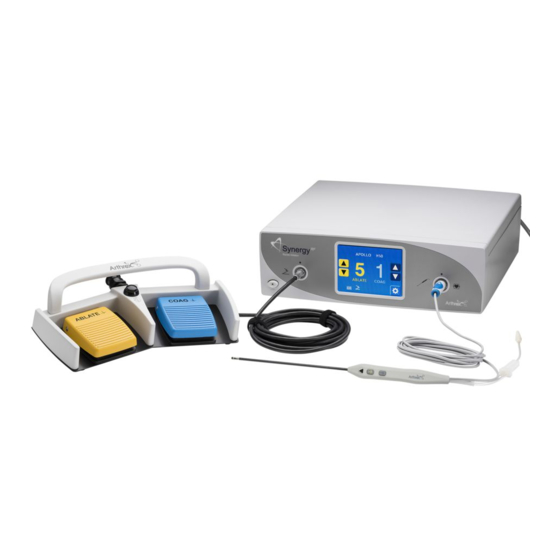
Product Drawings and References Synergy System Service Guide RF™ Connection Diagram Figure 1 Connection Diagram Table 1 Connection Elements 1. Generator/Console 2. Power Cord 3. Footswitch 4. Footswitch Cable Connector 5. RF Ablation Device (Probe) 6. Probe Cable Connector 7. Suction Tube Connector DFU-0276-4r0_fmt_en-US Page 8 of 50... -
Page 15: Product Layout
Product Drawings and References Synergy System Service Guide RF™ Product Layout 2.3.1 AR-9800 Console - Front View Figure 2 shows the front panel of the AR-9800 console. The features and symbols are identified in Table 2 below. Figure 2 Front Panel of Console Table 2 Front Panel Elements 1. -
Page 16: Ar-9800 Console - Rear View
2. Equipotential Bonding Pin with Stamped Equipotential Bonding Symbol 3. Address label 4. Fan 5. USB port (For use ONLY by service technicians) 6. Serial ports for Arthrex integration (to only be connected to IEC 60601-1 approved equipment) 7. Serial number label 8. Model number label 9. -
Page 17: Ar-9800 Display Messages
Table 4 below. Messages shaded in gray denote that Arthrex technical support should be contacted for further instructions. Error display messages reported to Arthrex technical services should include the Error Message and Error Code for reference (See Figure 4, Error display). -
Page 18: Figure 4 Error Screen Display
System Service Guide RF™ Message Explanation technical services. "Power Supply POST Failure" Power supply self-check failure, contact Arthrex technical services. "Power Supply PFC Voltage" Power supply self-check failure, contact Arthrex technical services. "Power Supply Excessive Voltage" Power supply is exceeding the voltage parameters, contact Arthrex technical services. -
Page 19: Applied Parts And Accessory Features
Product Drawings and References Synergy System Service Guide RF™ Applied Parts and Accessory Features 2.4.1 Synergy Footswitch (AR-9800-F) Figure 5 shows the Synergy Footswitch. The features and symbols are identified in Table 6 below. Figure 5 Standard Footswitch - Description Table 6 Elements of the Synergy Footswitch... -
Page 20: Apollo Rf® Probe
Product Drawings and References Synergy System Service Guide RF™ 2.4.2 Apollo RF® probe Figure 6 Standard Apollo probe - Description Table 7 Apollo probe - Description 1. Ablate Power Change Each time the button is pressed, the Ablation button setting increases by 1 unit. Activation increases ablation in a positive direction only. -
Page 21: Apollo Rf Service Probe
Product Drawings and References Synergy System Service Guide RF™ 2.4.3 Apollo Service probe Figure 7 Apollo Service probe - Description Table 8 Apollo Service probe - Description 1. Ablation Power Each time the button is pressed, the Ablation Change button setting increases by 1 unit. - Page 22 Product Drawings and References Synergy System Service Guide RF™ Apollo Service Probe Warnings: 1. If the equipment is used in a manner not specified by the manufacturer, the protection provided by the equipment may be impaired. 2. The maximum intended operating time of the Service Probe for a single use is 1 minute. 3.
-
Page 23: Technical Specifications
Technical Specifications Synergy System Service Guide RF™ 3.0 Technical Specifications Console Table 9 AR-9800 Console Specifications Width 40.64 cm (16.00 inches) Height 13.335 cm (5.250 inches) Depth 37.338cm (14.7 inches) Weight 6.8 kg (15 lbs.) Water protection IP22 Mains cable 10 A/250 V Power entry module IEC 320/C13... -
Page 24: Safety, Emc, And Regulatory Requirements
Technical Specifications Synergy System Service Guide RF™ Safety, EMC, and Regulatory Requirements Table 13 Safety, EMC, and Regulatory Requirements Parameter Parameter Value Class I IEC 60601-1 (protection against electric shock) FDA Class Class II System Classification EU Class Class IIb Health Canada Class Class 3 Domestic Certification... -
Page 25: Power Curves
Technical Specifications Synergy System Service Guide RF™ Power Curves DFU-0276-4r0_fmt_en-US Page 19 of 50... - Page 26 Technical Specifications Synergy System Service Guide RF™ DFU-0276-4r0_fmt_en-US Page 20 of 50...
- Page 27 Technical Specifications Synergy System Service Guide RF™ DFU-0276-4r0_fmt_en-US Page 21 of 50...
- Page 28 Technical Specifications Synergy System Service Guide RF™ DFU-0276-4r0_fmt_en-US Page 22 of 50...
- Page 29 Technical Specifications Synergy System Service Guide RF™ DFU-0276-4r0_fmt_en-US Page 23 of 50...
- Page 30 Technical Specifications Synergy System Service Guide RF™ DFU-0276-4r0_fmt_en-US Page 24 of 50...
-
Page 31: Setup
AC mains outlet. Please use the appropriate plug and a reliable ground conductor. Arthrex supplies separate power cords for the U.S. and Germany with the AR- 9800. Contact your Arthrex representative if you need a power cord that must meet the electrical standards of another country. -
Page 32: Replacing The Fuses
EMC compatibility. This device may cause interference to other devices in the near vicinity if not set up and used as Arthrex instructs. AR-9800 has been designed to accept EMC from other devices within the limitations as described in Section 10. -
Page 33: Basic Setup Procedure For The Ar-9800 Console
Inspect all cords for cracks, nicks and breaks. Inspect all connectors for damaged or missing parts. 1. Place the AR-9800 on a flat, dry surface, such as the AR-6481 Arthrex Arthroscopy cart. 2. Connect the receiver end of the power cord for the AR-9800 into the AC socket and the plug end to the facility AC mains supply. -
Page 34: Setting Up A Footswitch
W A R N I N G ! Use only Arthrex approved accessories. Other accessories may result in increased emissions or decreased immunity of the system. Contact your Arthrex representative for a complete list of accessories. DO NOT modify any accessory. - Page 35 Generator around metal objects. Wrapping cables around metal objects may induce currents that could lead to shock, fire or injury to the patient or surgical personnel. Only use Arthrex RF devices (Probes) that have been developed by Arthrex specifically for the Synergy console.
-
Page 36: Maintenance
If it becomes necessary to return the console or accessory devices to Arthrex for service, please clean them before shipping. If fluid or particles splash on the display, clean it with a micro-fiber cloth by gently wiping in a circular motion. -
Page 37: Technical Support
RF™ 6.0 Technical Support For assistance in using the products identified in the User’s Guide, contact an Arthrex representative or call the Arthrex Technical Support Hotline at 1-(888) 420-9393, Monday through Friday from 9:00 AM to 5:00 PM EST; at +49 89 909005 8800 or techsupport@arthrex.de from 8:00 AM to 5:00 PM CET. -
Page 38: Troubleshooting
If the problems persist, Contact Technical Support. If a devise must be returned, disinfect the Synergy System and send to Arthrex using the original packaging. Always send the corresponding accessory device and if applicable, the footswitch together with the console. Please enclose a brief explanation of the malfunction. Refer to Section 6 for Synergy Support Contact information. -
Page 39: End Of Life, Environmental Directives
For more information about where you can drop off your medical electronic equipment at the end of its useful life for recycling, please contact Arthrex Customer Service Department. -
Page 40: Electromagnetic Emissions
Synergy System Service Guide RF™ 10.0 Electromagnetic Emissions Table 15 Guidance and Manufacturer’s Declaration – Electromagnetic Emissions The AR-9800 Synergy system is intended for use in the electromagnetic environment specified below. The customer or the user of the AR-9800 Synergy system should assure that it is used in such an environment. -
Page 41: Table 17 Guidance And Manufacturer's Statement - Electromagnetic Immunity
Synergy System Service Guide RF™ Table 17 Guidance and Manufacturer's Statement - Electromagnetic Immunity The AR-9800 Synergy System is intended for use in the electromagnetic environment specified below. The customer or the user of the AR-9800 Synergy System should ensure that it is used in such an environment. - Page 42 Synergy System Service Guide RF™ Immunity test IEC 60601 test level Compliance level Electromagnetic environment - guidance Power 30 A/m 30 A/m @ 50 & 60 Hz Power frequency frequency magnetic fields should (50/60 Hz) be at levels characteristic magnetic field of a typical location in a IEC 61000-4-8 typical commercial or...
- Page 43 Synergy System Service Guide RF™ Table 17 (cont.) Guidance and Manufacturer's Statement - Electromagnetic Immunity The AR-9800 Synergy System is intended for use in the electromagnetic environment specified below. The customer or the user of the AR-9800 Synergy System should ensure that it is used in such an environment.
- Page 44 Synergy System Service Guide RF™ Immunity IEC 60601 Compliance Electromagnetic environment - guidance test test level level abnormal performance is observed, additional measures may be necessary, such as re-orienting or relocating the Model AR-9800 b Over the frequency range 150 kHz to 80 MHz, field strengths should be less than 3 V/m. DFU-0276-4r0_fmt_en-US Page 38 of 50...
-
Page 45: Table 18 Guidance And Manufacturer's Statement - Recommend Separation
Synergy System Service Guide RF™ Table 18 Guidance and Manufacturer's Statement – Recommend Separation Recommended separation distances between portable and mobile RF communications equipment and the Model AR-9800 The Model AR-9800 Synergy System is intended for use in an electromagnetic environment in which radiated RF disturbances are controlled. -
Page 46: Basic System Communication Plan
Synergy System Service Guide RF™ 11.0 Basic System Communication Plan Synergy RF System Basic Block Diagram Power Supply User System Interface System Controller Front Panel Display DFU-0276-4r0_fmt_en-US Page 40 of 50... -
Page 47: Preventative Maintenance Document (Optional)
Preventative Maintenance Inspection Form 12.0 Preventative Maintenance Document (Optional) AR-9800 Arthrex Synergy RF™ Console Technician: _________________________________ Date: _____________________________ Facility: ______________________________________________________________________ Department: __________________________________________________________________ Serial number: _____________________ Model Number: __________________________ Software Version Level: __________________________ : __________________________ : _____________________________ Each step must be performed in the order provided on this form. Sign off each step as it is performed, prior to the next step. - Page 48 Supply main input Plug Equipotential Bonding Pin with Stamped Equipotential Bonding Symbol Address Label USB port (For use ONLY by Service technicians) Serial ports for Arthrex integration (to only be connected to IEC 60601-1 approved equipment) Serial number label Model number label...
- Page 49 Electrosurgical Analyzer. A Calibrated Electrical Safety Analyzer will be required to complete the electrical safety test. Procedure: Indicate a PASS/Fail for each item. Any failure indicates that the device will need to be sent to Arthrex for evaluation. Visual Inspection...
- Page 50 Preventative Maintenance Inspection Form Touch Screen Initials Action Pass/Fail Make sure the ablate number increases when pressing the yellow ablate "Up Button" [3]. The ablate power [1] will increase in increments of 1. Make sure the ablate number decreases when pressing the yellow ablate "Down Button"...
- Page 51 Preventative Maintenance Inspection Form Additional Screen Information Present/Not Initials Action Present Make sure you are able to see the intelligent device recognition symbol [6] Make sure you are able to see the footswitch symbol if a footswitch is connected to the RF device. [7] Make sure you are able to see the time burst symbol if time burst is active [8].
- Page 52 If all steps have passed or measured within tolerance then the device can be put back into service. If an item has failed please contact Arthrex Technical Assistance Center at Toll-Free Technical Support: 1-(888) 420-9393, Monday through Friday, 9:00 AM – 5:00 PM EST.
- Page 53 Preventative Maintenance Inspection Form Appendix: If a possible solution is displayed on the error message, please try to troubleshoot it before proceeding with the PM guide. If Arthrex support is needed please call the Arthrex Support Line. Message Possible Solution A button on the foot switch is stuck.
- Page 54 Relay Failure Services. Power supply self-check failure, contact Arthrex Technical RF Output Failure Services. Touchscreen Circuit Failure Touch panel failure, contact Arthrex technical services. Critical failure, Make note of message displayed. Call Arthrex Red Fault Message Service DFU-0276-4r0_fmt_en-US PM – 8/8...
- Page 55 Synergy System Service Guide RF™ This page intentionally left blank DFU-0276-4r0_fmt_en-US Page 49 of 50...
- Page 56 Synergy System Service Guide RF™ Arthrex, Inc. 1370 Creekside Blvd. Naples, FL 34108-1945 USA www.arthrex.com Customer Service 1-(800) 934-4404 Toll-Free Technical Support: 1-(888) 420-9393, Monday through Friday, 9:00 AM – 5:00 PM EST. Arthrex GmbH Erwin-Hielscher-Straße 9 81249 München, Germany Tel:+49-89-90 90 05-0 www.arthrex.de...
Need help?
Do you have a question about the SynergyRF AR-9800 and is the answer not in the manual?
Questions and answers