Table of Contents
Advertisement
Quick Links
Advertisement
Table of Contents

Subscribe to Our Youtube Channel
Related Manuals for Protec 6100


Summary of Contents for Protec 6100
- Page 1 6100 SINGLE LOOP DIGITAL ADDRESSABLE FIRE ALARM CONTROL PANEL INSTALLATION AND COMMISSIONING MANUAL Protec Fire Detection plc, Protec House, Churchill Way, Nelson, Lancashire, BB9 6RT, ENGLAND +44 (0) 1282 717171 www.protec.co.uk sales@protec.co.uk...
-
Page 2: Appendix
Update to BS5839 references Change to BSI NB Number 16/05/2019 Refer to ECN4363 Change to operating temperature range in section 10.0 Change to copyright year 10/02/2020 Refer to ECN4463 N93-572-88 Issue 12 NH Page 2 of 52 © Protec Fire Detection plc 2020... -
Page 3: Table Of Contents
ITEMS AND INFORMATION REQUIRED PRIOR TO COMMISSIONING ..........7 Site information required to commission the 6100 ................7 Items required to commission the 6100 using the windows software ..........7 INTRODUCTION AND KEY FEATURES ....................8 6100 CABLING REQUIREMENTS ......................9 General ............................ - Page 4 Displaying Panel Diagnostic Data ....................41 7.28 Displaying Panel Manufacturing Details ..................42 7.29 Connecting the 6100 to a PC ..................... 43 7.30 Restarting the 6100 ........................43 PROGRAMMING THE SYSTEM USING THE WINDOWS SOFTWARE SUITE ......... 44 GENERAL SYSTEM OPERATION ...................... 44 Panel Initialisation ..........................
-
Page 5: Important Notes - Please Read Carefully
Important Notes – PLEASE READ CAREFULLY • Both the 6100 user manual and this manual should be thoroughly read and understood before installation and commissioning is undertaken. • The 6100 and its associated connections must be installed, commissioned and maintained by a suitably trained, skilled and competent person. -
Page 6: Standards, Directives And Regulations Information
The policy of Protec Fire Detection plc is one of continuous improvement. As such we reserve the right to make changes to product specifications at any time and without prior notice. Errors and omissions excepted. -
Page 7: Items Supplied With The 6100
Coincidence operation Items required to commission the 6100 using the windows software • Suitable PC with a USB port ( please consult the 6100 programming manual for details of the recommended PC specification ) • 6100 commissioning software Windows program ( and associated dongle if the system is managed ) •... -
Page 8: Introduction And Key Features
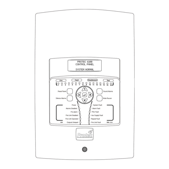
Introduction and Key Features The 6100 is a single loop fire alarm control panel incorporating an integrated power supply and high power loop driver circuit that communicates to a maximum of 192 Protec 6000Plus series detectors / sounders.and 6000 series interfaces. -
Page 9: 6100 Cabling Requirements
BS 5839 Part 1 : 2017 ( or any document superseding it ). Mains Input Rating Label The mains rating label is located on the inner door of the 6100 and should be consulted before starting installation. The label details the working voltage, frequency and maximum current of the 6100. -
Page 10: Fire Link Wiring
The fire link output is monitored for open and short circuit cable faults and, when used, must only connect to the Protec 6100 fire link end of line module. If the fire link output is not used it must be terminated locally in the panel ( consult section 10.0 for details ). - Page 11 Total loop load alarm (mA) Loop Length ( meters ) 1000 1050 1100 1150 1200 1250 1300 1350 1400 1450 1500 Total loop load alarm (mA) N93-572-88 Issue 12 NH Page 11 of 52 © Protec Fire Detection plc 2020...
-
Page 12: Insulation Testing Of Cabling Prior To Connection
Insulation Testing of Cabling Prior to Connection Before connecting any external cables to any field device or the 6100, tests should be carried out using a 500V ® ‘ DC insulation tester ( ‘ Megger ). If tests are performed the insulation readings between each cable core, and each cable core and earth must be greater than 10MW. -
Page 13: Installing The 6100
Installing the 6100 The 6100 may be surface or flush mounted ( no extra bezel is required when flush mounting ). The 6100 circuit board is fully enclosed within a sealed control PCB housing. The control PCB housing must never be opened. If the 6100 requires repair it must be sent back to the Protec factory. -
Page 14: Disconnection Of The Fire Brigade Panel (Fbp) Connections
Disconnection of the Fire Brigade Panel (FBP) Connections If the 6100 is equipped with the optional Fire Brigade Panel control interface ensure that the ribbon cable and earthing cable are disconnected from the rear of the controller as shown in figure 6.1. -
Page 15: Removal Of The Control Pcb Housing
Unscrew and remove the four mounting screws on the control PCB housing. Carefully lift away the control PCB housing from the plastic enclosure. See figure 6.2. The 6100 control PCB housing and all screws should be stored in the cardboard carton away from the place of work where they will not get damaged. -
Page 16: Preparing The Mounting Position And Cable Entries
A four way brass earth block is supplied with the 6100. Three locations are provided for this in the 6100 back box. This allows the best location to be selected depending on wiring entry requirements. -
Page 17: Connecting The Standby Batteries
), carefully push the spade connectors of the 6100 battery leads onto the relevant battery terminals ( illustrated in figure 6.4 ). Please note that at this point the 6100 will not power up until the mains supply is connected. Figure 6.4... -
Page 18: Refitting The Control Pcb Housing
Connecting the Addressable Loop Wiring The 6100 loop wiring must always be connected as a complete loop ( LA + and LA - connections ) to each device, then back to the panel again ( LB + and LB - connections ). Please see figure 6.5 and refer to figure 4.0. -
Page 19: Connecting The Fire Link Wiring
( see appendix 1 for stock code ). The End of Line Module must be fitted in the remote equipment, and not in the 6100. If the fire link end of line module is not required, the fire link output must still be terminated with an end of line resistor. -
Page 20: Connecting The Mains Cabling
‘OFF’ position. Pay particular attention that the incoming mains cable is segregated from all other cables within the 6100 enclosure. Ensure the incoming earth cable is firmly connected to the Main PCB ( see figure 6.11 ), and that the earth cable from the Main PCB is securely connected to the brass earth terminals within the back-box. -
Page 21: Connecting The Fire Brigade Panel Controller
Switch the fused isolator to the ‘ON’ position. The green ‘Power’ indicator will illuminate and, assuming all other connections are correct, the 6100 should show one fault on the display ( a ‘panel reset ‘ fault ). The 6100 is now ready to be programmed and commissioned. -
Page 22: Commissioning The 6100
Commissioning the 6100 The 6100 can be commissioned in a basic manner by using the menus, or more extensively using the Windows programming software. It is recommended that the Windows software is used ( for a list of compatible PC hardware and operating systems please consult the 6100 programming manual ). -
Page 23: Loop Device Class Programming
Silence, Reset, IReset, Sound Alarms and Accept Class Loop devices programmed into any of these classes will mimic the relevant 6100 button press when activated. The loop device itself must be set to non-latching, but not programmed as non-latching on the 6100. -
Page 24: Loop Device Sensitivity Programming
This setting is only applicable to automatic detectors and allows two detection sensitivities to be programmed. The 6100 offers a range of sensitivities that can be used to tailor the response of the detector to suit individual site conditions. The 6100 supports the following sensitivities. -
Page 25: Talking Sounder Programming Considerations
Talking Sounder Programming Considerations The 6100 supports Protec talking sounders and special consideration must be given to them when programming. Talking sounders contain several pre-set messages that the control panel activates when required. Talking sounders and non-talking output devices must not be mixed in the same output groups. -
Page 26: Fire Link Operation
The fire link output activates within one second of the panel entering the alarm state ( if a Fire Link delay has not been programmed ). The following 6100 activation’s will not activate the Fire Link: • Activation from a device programmed as Silence, Reset, IReset, Sound Alarms, Accept or Invisible Switch class •... -
Page 27: Global Fire Contact Operation
7.10 Global Fault Contact Operation The 6100 will operate the global fault contacts under any fault condition ( including when the panel is un-powered ). The fault contacts connections are shown on the terminal label in the non fault state. -
Page 28: Conventional Alarm Output Operation
The usual reason for using T1/T2 programming is to delay activation of sounders until the premises management reach the 6100 (T1 delay) and instigate a search time (T2 delay). The source of the alarm can then be investigated, and the panel reset if required. - Page 29 Figure 7.0 – 6100 Engineer (Access level 3) Menu Structure Exchange Devices View Faults See Section 7.19 Refer to User Manual View Disablements Disable a device Refer to User Manual See Section 7.20 Clear System Faults Device RVAV Refer to User Manual See Section 7.21...
-
Page 30: Programming The Coverage Volume Of Visual Alarm Devices (Vads)
During the logging phase the 6100 drives the loop from sides A and B, all relevant devices connected to the loop are logged and stored in memory ( devices will not be logged if the 6100 does not support the device type, or the software version of the device is not supported by the 6100 ). - Page 31 Displayed when the 6100 has successfully logged and mapped the loop. Mapping data is now in memory ready for loop devices to be allocated. MAPPING FAILED Displayed if the 6100 could not successfully log or map the loop. This could be because there are more than 192 devices on the loop. Figure 7.1...
-
Page 32: Programming Loop Device Address Data
To de-allocate a device from this address select a SNUM of 000000, this then makes the loop device free to swap to another address or it can be left de-allocated ( the 6100 will not process a de-allocated device ). - Page 33 Press the ¿ key at any time to store any changes, the 6100 will warn that changes are to be made to the site data and the panel will reset and reboot as shown in figure 7.6. Figure 7.6...
-
Page 34: Exchanging Loop Devices
Enter the user code supplied with the system and press the ¿ key to access the menus. Scroll to the EXCHANGE DEVICES menu and press the ¿ key. The 6100 is now in exchange devices mode ( figure 7.7 ). Up to 8 loop devices may be exchanged at a time. -
Page 35: Disabling / Enabling A Loop Device
The whole zone must be enabled. If a device is being taken out of disablement, but is in the alarm state, then the 6100 will display a warning screen and then automatically perform a system reset. This is done to avoid the 6100 immediately entering the alarm state when the device is normalised. -
Page 36: Loop Device Remote Visual Address Verification ( Rvav )
Devices set to RVAV operation cannot detect a fire At the DEVICE RVAV menu press the ¿ key the 6100 will warn that devices programmed to RVAV will not detect fires. The user may then accept this condition by pressing the ¿ key, or decline by pressing the ▲, ▼, ◄... -
Page 37: Editing Device Location Text
ZONE 28 ZONE TEXT FOR ZONE 28 ^ ....N93-572-88 Issue 12 NH Page 37 of 52 © Protec Fire Detection plc 2020... -
Page 38: Clearing The Historic Fire Event Log
Press the ▲, ▼, ◄ or ► keys to return to the main menu without clearing the log. Figure 7.17 Clear General Event Log warning display All general log data will be permanently deleted Continue ? N93-572-88 Issue 12 NH Page 38 of 52 © Protec Fire Detection plc 2020... -
Page 39: Displaying Loop Device Data
The DISPLAY LOOP DEVICE DATA menu allows the engineer to view data relating to any loop device logged onto the 6100. During the commissioning phase this feature may be useful to determine the state of each loop device, the reply values for each channel and any missed replies. - Page 40 Figure 7.22 Display loop device data screen 5 An * indicates which is currently running Day or Night sensitivity Day sense office Night sense office class automatic N93-572-88 Issue 12 NH Page 40 of 52 © Protec Fire Detection plc 2020...
-
Page 41: Displaying Panel Diagnostic Data
Press the ▲ or ▼ keys to move through the data screens. Press the ¿ key in any screen to return to the main menu. Screen 1 displays various levels associated with the 6100 power supplies. Figure 7.23 Typically Panel Diagnostic data screen 1... -
Page 42: Displaying Panel Manufacturing Details
Press the ¿ key to return to the main menu Figure 7.26 Display Panel Data display Sw ver 1.25 Sp ver 0.00 snum 61000100 sf rev 0001 N93-572-88 Issue 12 NH Page 42 of 52 © Protec Fire Detection plc 2020... -
Page 43: Connecting The 6100 To A Pc
7.29 Connecting the 6100 to a PC The CONNECT TO PC USING USB menu allows the engineer to connect the 6100 to a PC in order download panel firmware or update and backup the site specific settings. Consult the 6100 Programming Manual for further details. -
Page 44: Programming The System Using The Windows Software Suite
The scan values are checked for stability; each scan value must be within 4 reply counts of any other for that channel. If a ‘noisy‘ device is detected the 6100 issues a ‘Device Failed Setup‘ event for that loop address and the device is not permitted to generate a fire. It will remain in fault until: The 6100 is restarted. -
Page 45: 10.0 6100 Technical Specification
2 x 12V 3.3Ah Sealed Lead Acid ( connected in series ) Battery Type Only use batteries recommended by Protec ( see appendix 1 ) Output Voltage 24 – 29V dc with mains present , 17 – 29V dc on batteries... -
Page 46: Appendix 1 List Of 6100 Spares And Accessories
Monitored for open and short circuit faults. Requires Protec end of line module Fire Link Output ( see appendix 1 ) if used to signal to a remote station, otherwise a 4.7kΩ ¼W ( ± 5% ) termination resistor must be connected locally in the 6100 Fire link Output Current When 20mA... -
Page 47: 6100 Control Pcb Housing
Appendix 2 6100 Control PCB Housing The diagram below shows the 6100 Control PCB housing and highlights the main connections and controls. Remote Alarm Mains cable input Monitored restraint conventional Monitored Class Change alarm outputs Auxiliary 24V input Global fire... -
Page 48: Appendix 3 Loop Devices Supported By The 6100
6000/VAD/W/x (x = RED or WHITE) 6000/TSx/VAD (x = R or W depending on colour) * Any non 6000PLUS series detection device attached to this device is not supported by the 6100. N93-572-88 Issue 12 NH Page 48 of 52... -
Page 49: Appendix 4 6100 Event Descriptions
The alarm outputs have been disabled. Alarm outputs from loop devices, or connected to the conventional alarm outputs will not activate. FIRE LINK FAULT A fault has been detected on the fire link output. The fire link may not operate when the 6100 detects a fire. N93-572-88 Issue 12 NH Page 49 of 52... - Page 50 BATTERY FAULT The 6100 has detected a fault with the internal standby battery. This may be due to a fault with the batteries, or the connections to the batteries. The 6100 may not operate correctly in the event of a mains failure.
- Page 51 SITEFILE ERROR The revision of ‘site file’ in the 6100 is incompatible with the version of 6100 operating system. The correct ‘site file’ revision must be programmed into the 6100, or the operating system must be updated as required. N93-572-88 Issue 12 NH Page 51 of 52 ©...
- Page 52 Designed and manufactured in the United Kingdom N93-572-88 Issue 12 NH Page 52 of 52 © Protec Fire Detection plc 2020...
Need help?
Do you have a question about the 6100 and is the answer not in the manual?
Questions and answers