Table of Contents

Subscribe to Our Youtube Channel
Related Manuals for Protec 3500


Summary of Contents for Protec 3500
- Page 1 3500 CONVENTIONAL FIRE ALARM CONTROL PANEL USER MANUAL Protec Fire Detection PLC, Protec House, Churchill Way, Nelson, Lancashire, BB9 6RT. Telephone: +44 (0) 1282 717171 Fax: +44 (0) 1282 717273 Web: www.protec.co.uk Email: sales@protec.co.uk...
- Page 2 Document Revision Details Issue Modification Detail Author Date Issue 0 Document Creation 22/11/2013 Issue 1 Refer to ECN3504 14/05/2014 Issue 2 Refer to ECN3715 07/04/2015 N 93-585-83 Issue 2 AB Page 2 of 25 © Protec Fire Detection PLC 2015...
-
Page 3: Table Of Contents
Manual Detection ........................12 13.3 Coincidence Activation ........................ 12 13.4 Silencing the Alarms ........................12 13.5 Resetting the 3500 after an Alarm ....................13 13.6 New Zone in Alarm ........................13 13.7 Activating the Alarms Manually ....................13 14.0 3500 FIRE BRIGADE PANEL OPERATION ..................13 14.1... - Page 4 Clearing System Faults ....................... 15 16.0 APPENDIX 1 - 3500 SYSTEM SET UP RECORD ................16 17.0 APPENDIX 2 - 3500 FIRE AND FAULT EVENT LOG ................. 18 APPENDIX 3 – 3500 OPERATION QUICK REFERENCE GUIDE ............23 18.0 18.1 Entering Access Level 2 ......................
-
Page 5: Introduction
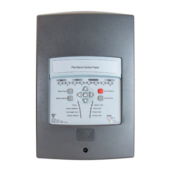
Introduction The 3500 is a conventional fire alarm control panel available in 2, 4 and 8 zone models. The 3500 incorporates all detection zone circuits, an integrated power supply and two fully monitored alarm circuits. The 3500 includes many programming and configuration features making it easy to integrate to a variety of site conditions. -
Page 6: User Responsibilities
Ensure that, where necessary, a suitable zone plan is displayed and kept up to date. Ensure that any relevant spare parts for system maintenance are held within the premises. N 93-585-83 Issue 2 AB Page 6 of 25 © Protec Fire Detection PLC 2015... -
Page 7: Routine Testing Of The System
Ensure no Manual Call Points or detectors are obstructed During the test you may wish to place the 3500 into weekly test mode (consult section 13.3) Operate a Manual Call Point or detector during normal working hours to ensure the fire alarm system operates correctly ... -
Page 8: 3500 Access Levels
Access Level 1 (General User) Access level 1 allows the general user to view the status of the 3500 at any time. Zone fire, fault, disablement and test states are clearly displayed as are any current system faults, disablements or delays. -
Page 9: 3500 Indications And Controls
General Test indicator. Code Entry and Menu Keys The keys in the centre of the 3500 are used to enter the user code (using keys 1, 2, 3 and 4) and are also used to navigate the menu system. -
Page 10: 3500 Fire Indications
3500 Fault Indications When the 3500 has detected a fault in any of the critical operating paths of the system it will display this on the front panel display. The internal buzzer will also pulse slowly. -
Page 11: Supply Fault
10.3 Access Level Indication If the 3500 panel is in access level 2 then the ‘Access Level’ will be illuminated. If the 3500 panel is in access level 3 then the ‘Access Level’ will be flashing. N 93-585-83 Issue 2 AB Page 11 of 25 ©... -
Page 12: System Delays
Activating alarm outputs as programmed, after any delays have expired. Activating the Global Fire contacts. 13.2 Manual Detection If a Manual Call Point is operated on the zone of a 3500 this is known as manual operation. The 3500 responds by; Illuminating the ‘General Fire’ indicator ... -
Page 13: Resetting The 3500 After An Alarm
Resetting the 3500 after an Alarm After the cause of the alarm has been determined (and entered in the fire alarm log book) the 3500 can be reset if required. Manual Call Points, if triggered, must first be reset locally. In access level 2 press ‘Silence Alarms’... -
Page 14: 3500 Access Level 2 User Options
15.2 Enabling Weekly Test Mode The 3500 allows all zones to be programmed into weekly test mode, this permits rapid verification of device operation on zones. In this mode, activations from zones sound the alarms for 10 seconds for verification purposes, after which the 3500 automatically resets and exits weekly test mode. -
Page 15: Testing The Panel Indications And Internal Buzzer
15.3 Testing the Panel Indications and Internal Buzzer The 3500 allows the front panel indications and internal buzzer to be tested. In this mode all indicators are momentarily illuminated and the internal buzzer sounded. If any indicators fail to illuminate, or the buzzer does not sound, note this in the system log and get the fault rectified immediately. -
Page 16: Appendix 1 - 3500 System Set Up Record
16.0 Appendix 1 - 3500 System Set up Record The engineer in charge of commissioning the system must complete this sheet. It is the only record of how the system has been configured and, as such, must be safely stored for future reference. - Page 17 ZONE ZONE DESCRIPTION / LOCATION / COMMENTS PROGRAMMING N 93-585-83 Issue 2 AB Page 17 of 25 © Protec Fire Detection PLC 2015...
-
Page 18: Appendix 2 - 3500 Fire And Fault Event Log
17.0 Appendix 2 - 3500 Fire and Fault Event Log The person appointed in charge of the fire alarm system must complete the relevant section of this sheet whenever a fire or fault event occurs on the system. Name of appointed responsible person …………………………………………………………………………………………………... - Page 19 3500 Fire Alarm System Event Log DATE TIME ZONE DETAILS ACTION REQUIRED COMPLETED NAME N 93-585-83 Issue 2 AB Page 19 of 25 © Protec Fire Detection PLC 2015...
- Page 20 DATE TIME ZONE DETAILS ACTION REQUIRED COMPLETED NAME N 93-585-83 Issue 2 AB Page 20 of 25 © Protec Fire Detection PLC 2015...
- Page 21 DATE TIME ZONE DETAILS ACTION REQUIRED COMPLETED NAME N 93-585-83 Issue 2 AB Page 21 of 25 © Protec Fire Detection PLC 2015...
- Page 22 DATE TIME ZONE DETAILS ACTION REQUIRED COMPLETED NAME N 93-585-83 Issue 2 AB Page 22 of 25 © Protec Fire Detection PLC 2015...
-
Page 23: Appendix 3 - 3500 Operation Quick Reference Guide
Performing a Weekly Test From access level 2 press button '2' to activate weekly test mode. Test a device on the relevant zone. The alarms will sound for 10 seconds, then the 3500 will automatically reset and exit test mode. -
Page 24: Appendix 4 - Zone Chart
19.0 Appendix 4 - Zone Chart It is intended that this chart be filled in and affixed near the 3500 control panel. Zone Number Description Details of person responsible for management of fire alarm system N 93-585-83 Issue 2 AB Page 24 of 25 ©... - Page 25 Protec Fire Detection PLC, Protec House, Churchill Way, Nelson, Lancashire, BB9 6RT. Telephone: +44 (0) 1282 717171 Fax: +44 (0) 1282 717273 Web: www.protec.co.uk Email: sales@protec.co.uk N 93-585-83 Issue 2 AB Page 25 of 25 © Protec Fire Detection PLC 2015...
Need help?
Do you have a question about the 3500 and is the answer not in the manual?
Questions and answers