Protec 6100 User Manual
Single loop digital addressable fire alarm control panel
Hide thumbs
Also See for 6100:
- Pc programming manual (32 pages) ,
- Installation and commissioning manual (52 pages)

Related Manuals for Protec 6100


Summary of Contents for Protec 6100
- Page 1 6100 SINGLE LOOP DIGITAL ADDRESSABLE FIRE ALARM CONTROL PANEL USER MANUAL Protec Fire Detection plc, Protec House, Churchill Way, Nelson, Lancashire, BB9 6RT, ENGLAND +44 (0) 1282 717171 www.protec.co.uk sales@protec.co.uk...
- Page 2 Section 14.0 amended, miscellaneous text tidied 17/01/2012 Refer to ECN3414 10/10/2013 Addition of WEEE data in section 1.0 22/06/2014 Refer to ECN3729 14/07/2015 Update to BS5839 references 16/05/2019 Refer to ECN4363 N93-571-87 Issue 5 NH Page 2 of 34 © Protec Fire Detection plc 2019...
-
Page 3: Table Of Contents
Power on Indication ........................12 Pre Alarm ............................12 Outputs Delayed ..........................12 10.0 SYSTEM DELAYS ..........................13 11.0 COINCIDENCE OPERATION ......................13 12.0 6100 RESPONSE TO AN ALARM ...................... 14 12.1 Automatic Detection ........................14 12.2 Manual Detection ........................14 12.3... - Page 4 Reset Button ..........................24 15.5 Disable Button ........................... 24 16.0 APPENDIX 1 - 6100 SYSTEM SET UP RECORD ................25 17.0 APPENDIX 2 - 6100 EVENT LOG ....................... 28 18.0 APPENDIX 3 – 6100 OPERATION QUICK REFERENCE GUIDE ............33 18.1...
-
Page 5: Introduction
). As the integrity and reliability of a fire alarm system is vital, the 6100 continuously monitors all critical paths for faults. The fire detection / alarm loop devices and wiring are constantly monitored to check for faults. The integrated power supply regularly performs self checks to ensure it is in full working order and that the stand-by batteries are in a good state. -
Page 6: User Responsibilities
Ensure that, where necessary, a suitable zone plan is displayed and kept up to date. • Ensure that any relevant spare parts for system maintenance are held within the premises. N93-571-87 Issue 5 NH Page 6 of 34 © Protec Fire Detection plc 2019... -
Page 7: Routine Testing Of The System
British Standards BS5839, or equivalent regional standards. The latest software and release notes are available freely via our website (www.protec.co.uk) for the lifetime of the product. N93-571-87 Issue 5 NH Page 7 of 34 ©... -
Page 8: Annual Test
Carry out a full wiring check in accordance with the testing and inspection requirements of the relevant National wiring regulations ( I.E.E regulations for the UK ). N93-571-87 Issue 5 NH Page 8 of 34 © Protec Fire Detection plc 2019... -
Page 9: 6100 Access Levels
Access Level 1 ( General User ) Access level 1 allows the general user to view the status of the 6100 at any time. Zone fire, fault, disablement and test states are clearly displayed as are any current system faults and disablements. -
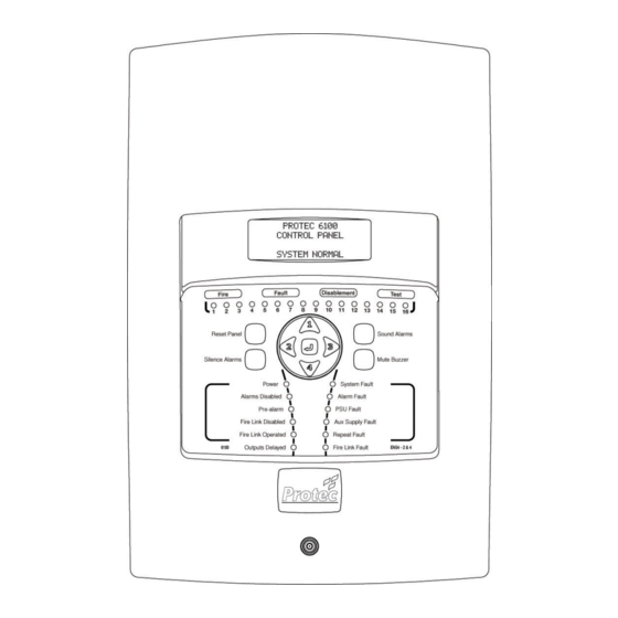
Page 10: 6100 Indications And Controls
General Test indicator. Code Entry and Menu Navigation Keys The keys in the centre of the 6100 are used to enter the user code ( using keys 1, 2, 3 and 4 ) and are also used to navigate the menu system. -
Page 11: 6100 Fire Indications
6100 Fault Indications When the 6100 has detected a fault in any of the critical operating paths of the system it will display this on the front panel display. The internal buzzer will also pulse slowly. -
Page 12: Supply Fault
General Fault indicator will be illuminated accompanied by the ‘Aux Supply Fault’ indicator. Repeat Panel Fault A fault has been detected on a repeat panel connected to the 6100, or the wiring to the repeat panel is faulty. The ‘General Fault’ indicator will be illuminated, accompanied by the Repeat Fault indicator. -
Page 13: System Delays
10.0 System Delays Delays may have been programmed into the 6100 at commissioning time to allow a predetermined delay time from zone activation until, • The alarm outputs activate • The fire link activates Delays may be used in order to allow time for the cause of the activation to be investigated by the premises management. -
Page 14: 6100 Response To An Alarm
12.0 6100 Response to an Alarm 12.1 Automatic Detection If a detector ( smoke, heat etc. ) activates on a zone of the 6100 this is known as an automatic operation. The 6100 responds by ; • Illuminating the ‘General Fire’ indicator. -
Page 15: 6100 Status Displays
13.0 6100 Status Displays At any given time the 6100 will be in one of three main states. These are the normal condition, the fault / disablement/test condition or the fire condition. 13.1 The System Normal Display When the 6100 does not have any fires, faults, disablements or tests it is in the System Normal condition. -
Page 16: The Fire Alarm Display
13.3 The Fire Alarm Display The 6100 enters the alarm state if one or more loop devices have triggered ( this may be because an automatic detector has sensed a fire, or a Manual Call Point has been operated ). -
Page 17: 6100 User Menus
14.0 6100 User Menus 14.1 Entering the 6100 Menu System When the user code is entered at access level 1 the ‘user level accessed’ screen will be displayed as shown in figure 14.0. The Sound Alarms, Silence Alarms, Reset Panel and Mute Buzzer buttons are now enabled. -
Page 18: Viewing Faults And Disablements
¿ key. The first event is displayed, ( illustrated in figure 14.1 / 14.3 ) If there are no current events the 6100 will show the screen illustrated in figure 14.2 / 14.4, and an error tone will be issued. -
Page 19: Clearing System Faults
Test Indications Display ***lcd * test *line *1 *** ***lcd * test *line *2 *** ***lcd * test *line *3 *** ***lcd * test *line *4 *** N93-571-87 Issue 5 NH Page 19 of 34 © Protec Fire Detection plc 2019... -
Page 20: Setting A Zone Into Walk Test Mode
Setting a Zone Into Walk Test Mode The 6100 allows a single zone at a time to be set to walk test mode. In walk test mode a loop device can be functionally tested and, after a predetermined time, the 6100 will automatically reset. -
Page 21: Disabling Alarm And Fire Link Outputs
Setting the Date and Time The SET DATE AND TIME menu allows the user to set the current date and time used by the 6100. The time is entered in 24-hour format and is used when time stamping alarm, fault, disablement or test events. -
Page 22: Viewing The Alarm Counter
Using the ◄ and ► keys navigate to the VIEW FIRE EVENT LOG menu and press the ¿ key. The latest fire is displayed first, as shown in figure 14.11. If there are no fires in the log the 6100 will show the screen illustrated in figure 14.12, and issue an error tone. -
Page 23: Viewing The General Event Log
Using the ◄ and ► keys navigate to the VIEW GENERAL EVENT LOG menu and press the ¿ key. The latest event is displayed first, as shown in figure 14.13 If there are no events in the log the 6100 will show the screen illustrated in figure 14.14, and issue an error tone. -
Page 24: 6100 Fire Brigade Panel Operation (Australian Markets)
90 degrees. Confirmation of this is given by illumination of the 'OPERATED' indicator and audible feedback from the internal buzzer. Once activated all button controls (detailed below) are available. If programmed to do so the LCD on the 6100 will turn off upon activation of the FBP controller. 15.2... -
Page 25: Appendix 1 - 6100 System Set Up Record
16.0 Appendix 1 - 6100 System Set up Record The engineer in charge of commissioning the system must complete this sheet. It is the only record of how the system has been configured and, as such, should be safely stored for future reference. - Page 26 ZONE ZONE DESCRIPTION / LOCATION PROGRAMMING N93-571-87 Issue 5 NH Page 26 of 34 © Protec Fire Detection plc 2019...
- Page 27 ZONE ZONE DESCRIPTION / LOCATION PROGRAMMING N93-571-87 Issue 5 NH Page 27 of 34 © Protec Fire Detection plc 2019...
-
Page 28: Appendix 2 - 6100 Event Log
17.0 Appendix 2 - 6100 Event Log The person appointed in charge of the fire alarm system should complete the relevant section of this sheet whenever an event ( fire or fault ) occurs on the system. Name of the person in charge of the fire alarm system …………………………………………………………………………………………………... - Page 29 6100 Fire Alarm System Event Log DATE TIME ZONE DETAILS ACTION REQUIRED COMPLETED NAME N93-571-87 Issue 5 NH Page 29 of 34 © Protec Fire Detection plc 2019...
- Page 30 DATE TIME ZONE DETAILS ACTION REQUIRED COMPLETED NAME N93-571-87 Issue 5 NH Page 30 of 34 © Protec Fire Detection plc 2019...
- Page 31 DATE TIME ZONE DETAILS ACTION REQUIRED COMPLETED NAME N93-571-87 Issue 5 NH Page 31 of 34 © Protec Fire Detection plc 2019...
- Page 32 DATE TIME ZONE DETAILS ACTION REQUIRED COMPLETED NAME N93-571-87 Issue 5 NH Page 32 of 34 © Protec Fire Detection plc 2019...
-
Page 33: Appendix 3 - 6100 Operation Quick Reference Guide
18.7 Testing the Indicators and Internal Buzzer From access level 2 navigate to the TEST INDICATIONS menu then press ¿ the 6100 will perform a full indicator test. Do not press any buttons while the test is in progress. 18.8 Setting the Date and Time From access level 2 navigate to the SET DATE AND TIME menu then press ¿... - Page 34 Designed and manufactured in the United Kingdom N93-571-87 Issue 5 NH Page 34 of 34 © Protec Fire Detection plc 2019...
Need help?
Do you have a question about the 6100 and is the answer not in the manual?
Questions and answers