Table of Contents

Related Manuals for Protec Digilite DL500


Summary of Contents for Protec Digilite DL500
- Page 1 Digilite® DL500 EMERGENCY LIGHTING SUPERVISORY PANEL INSTALLATION AND COMMISSIONING MANUAL Protec Fire Detection plc, Protec House, Churchill Way, Nelson, Lancashire, BB9 6RT, ENGLAND +44 (0) 1282 717171 www.protec.co.uk sales@protec.co.uk...
- Page 2 Document Revision Details Issue Modification Detail Author Date Document Creation 05/02/2015 N93-582-01 Issue 1 NH Page 2 of 42 © Protec Fire Detection plc 2015...
-
Page 3: Table Of Contents
Displaying Loop Device Data ..................... 30 10.15 Displaying Panel Diagnostic Data ....................31 10.16 Displaying Panel Manufacturing Details ..................32 10.17 Displaying the Programmed Network Configuration Settings ............ 32 N93-582-01 Issue 1 NH Page 3 of 42 © Protec Fire Detection plc 2015... - Page 4 LIST OF DIGILITE® DL500 SPARE PARTS AND ACCESSORIES ........ 37 APPENDIX 2 DIGILITE® DL500 MECHANICAL DIMENSIONS ............. 37 APPENDIX 3 DIGILITE® DL500 CONTROL PCB HOUSING ..............38 APPENDIX 4 DIGILITE® DL500 EVENT DESCRIPTIONS ..............39 N93-582-01 Issue 1 NH Page 4 of 42 © Protec Fire Detection plc 2015...
-
Page 5: Important Notes - Please Read Carefully
This equipment has been manufactured in conformance with the requirements of all applicable EU council directives. The policy of Protec Fire Detection plc is one of continuous improvement and as such we reserve the right to make changes to product specifications at any time and without prior notice. Errors and omissions excepted. -
Page 6: Glossary Of Terms
Slave Interface An interface designed to monitor the status of a lamp, usually used on central systems. This interface generally has no control functionality. N93-582-01 Issue 1 NH Page 6 of 42 © Protec Fire Detection plc 2015... -
Page 7: List Of Device Types Compatible With The Digilite® Dl500
List of Device Types Compatible with the Digilite® DL500 Table 2.0 gives a list of loop devices that are compatible with the Digilite® DL500 , along with a brief description of each device. For full details of the range please contact Protec. Table 2.0. -
Page 8: Items Supplied With The Digilite® Dl500
Digilite® DL500 Windows Configuration Tool ( contact Protec for details of this ) • Digilite® DL500 Programming Manual ( available upon request, or from the Protec website ) • USB 2.0 Lead ( Type A male to Type B male 2 metre maximum length ), as illustrated below •... -
Page 9: Introduction And Key Features
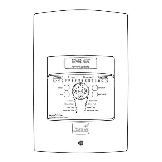
Introduction and Key Features The Protec Digilite® DL500 Emergency Lighting Supervisory Panel has been design to automate required scheduled testing of emergency lighting fittings in a building, as stipulated in BSEN62034 and BS5266 part 8. The Digilite® DL500 has been designed and manufactured in the UK using the latest technology and processes. -
Page 10: Digilite® Dl500 Cabling Requirements
( cable screen and / or drain wire is classed as earth ), and that the earth wiring does not touch any other connections, or any other earthed points. N93-582-01 Issue 1 NH Page 10 of 42 © Protec Fire Detection plc 2015... -
Page 11: Network Interface Wiring
Digilite® DL500. Equipment connected to the cabling during insulation tests will be damaged by the high voltages used, invalidating any warranty. Do not test IP network cabling N93-582-01 Issue 1 NH Page 11 of 42 © Protec Fire Detection plc 2015... -
Page 12: Installing The Digilite® Dl500
). The Digilite® DL500 circuit board is fully enclosed within a sealed control PCB housing. The control PCB housing must never be opened. If the Digilite® DL500 requires repair it must be sent back to the Protec factory. -
Page 13: Removal Of The Control Pcb Housing
The Digilite® DL500 control PCB housing and all screws should be stored in the cardboard carton away from the place of work, where they will not get damaged. Figure 9.1 Removal of the Digilite® DL500 Control PCB Housing N93-582-01 Issue 1 NH Page 13 of 42 © Protec Fire Detection plc 2015... -
Page 14: Removal Of The Optional Tcp/Ip Interface Pcb And Data Cable
Store the TCP/IP Interface PCB, Data cable and Screws in a safe dry place for use later. Figure 9.2 Removal of the (optional) TCP/IP Interface Card and Data Cable Screws Data connection cable to main panel N93-582-01 Issue 1 NH Page 14 of 42 © Protec Fire Detection plc 2015... -
Page 15: Preparing The Mounting Position And Cable Entries
These fit into the back-box and must be secured with the two plastic tie-wraps provided ( as shown in figure 9.3 ). Only use batteries supplied or recommended by Protec. The internal charger has been specifically designed to maintain the charge voltage at an optimum level for these batteries over the entire operating temperature range in order to maximise the life of the batteries. -
Page 16: Refitting The Tcp/Ip Interface And Data Cable
Finally, reconnect the data cable to the communications socket on the TCP/IP Interface, pushing it fully home. Figure 9.4 Installation of the (optional) TCP/IP Interface Card and Cabling RJ45 Network Connector Communications socket N93-582-01 Issue 1 NH Page 16 of 42 © Protec Fire Detection plc 2015... -
Page 17: Connecting The Standby Batteries
Please note that at this point the Digilite® DL500 will not power up until the mains supply is connected. Figure 9.5 Standby battery connections battery Black lead battery lead OBSERVE POLARITY WHEN CONNECTING THE BATTERY LEADS N93-582-01 Issue 1 NH Page 17 of 42 © Protec Fire Detection plc 2015... -
Page 18: Connecting The Tcp/Ip Interface Data Cable
PCB cassette, making sure it is pushed fully home. Figure 9.6 Location of the TCP/IP data cable socket on the rear of the Digilite® DL500 PCB cassette. TCP/IP Lead Connector N93-582-01 Issue 1 NH Page 18 of 42 © Protec Fire Detection plc 2015... -
Page 19: Refitting The Control Pcb Housing
Figure 9.8 Auxiliary 24V Output and Control Input Details Auxiliary 24V Output Control 1 and 2 Input N93-582-01 Issue 1 NH Page 19 of 42 © Protec Fire Detection plc 2015... -
Page 20: Connecting The Mains Cabling
Figure 9.9 Power Supply Terminal Connection Details Figure 9.10 Mains Wiring Connections and Restraining Clamp Reserved cable entry position Incoming mains wiring Mains wiring clamp N93-582-01 Issue 1 NH Page 20 of 42 © Protec Fire Detection plc 2015... -
Page 21: Re-Fitting The Door
Digilite® DL500 should show the 'System Normal' screen. The Digilite® DL500 is now ready to be programmed and commissioned. N93-582-01 Issue 1 NH Page 21 of 42 © Protec Fire Detection plc 2015... -
Page 22: Commissioning The Digilite® Dl500
Upon momentary activation of the Control 1 input the buzzer on the Digilite® DL500 is muted and the current state of the Digilite® DL500 is accepted. N93-582-01 Issue 1 NH Page 22 of 42 © Protec Fire Detection plc 2015... - Page 23 Restart System Refer to User Manual See Section 11.1 Log Loop Devices Exit Menu See Section 10.6 Refer to User Manual Program Address Data See Section 10.7 N93-582-01 Issue 1 NH Page 23 of 42 © Protec Fire Detection plc 2015...
-
Page 24: Logging Loop Devices
Logging = 001 ( 000 ) the number of logged devices process compared to those stored in the panel This field indicates the number of loop devices logged N93-582-01 Issue 1 NH Page 24 of 42 © Protec Fire Detection plc 2015... -
Page 25: Programming Loop Device Address Data
Setup the Test Group here A – means the device is stored in • the memory but has not been Setup MAINT or logged NON-MAINT here N93-582-01 Issue 1 NH Page 25 of 42 © Protec Fire Detection plc 2015... -
Page 26: Disabling And Enabling An Individual Device
DEVICE BUZZER ENABLED Figure 10.4 Device Disablement Screen Loop address Indicates if address is ENABLED or DISABLED ADDRESS 345 ENABLED Programmed address text ADDRESS TEXT XXXXXXX N93-582-01 Issue 1 NH Page 26 of 42 © Protec Fire Detection plc 2015... -
Page 27: Disabling And Enabling A Test Group
DEVICE BUZZER ENABLED Figure 10.6 Group Disablement Screen Test group Indicates if group is ENABLED or DISABLED GROUP 18 ENABLED Programmed group text GROUP TEXT XXXXXXXXXX N93-582-01 Issue 1 NH Page 27 of 42 © Protec Fire Detection plc 2015... -
Page 28: Editing Device Location Text
GROUP 16 GROUP TEXT FOR ZONE 16 ^ ....N93-582-01 Issue 1 NH Page 28 of 42 © Protec Fire Detection plc 2015... -
Page 29: Clearing The Historic Test Event Log
Press the Back or Escape keys to return to the main menu without clearing the log. Figure 10.10 Clear General Event Log warning display All general log data will be permanently deleted Continue ? N93-582-01 Issue 1 NH Page 29 of 42 © Protec Fire Detection plc 2015... -
Page 30: Displaying Loop Device Data
Enhanced loop device data screen Address 001 LEDDRV Number of missed replies GROUP GG Device reply channels shown here shown here ch1 ch2 ch3 MR=000 ADDRESS TEXt XXXXXXXx N93-582-01 Issue 1 NH Page 30 of 42 © Protec Fire Detection plc 2015... -
Page 31: Displaying Panel Diagnostic Data
24V output. Auxiliary data OK is normal Internal loop driver Aux 24v = OK ( 861) SC means short circuit fault values loop ol val = 405 N93-582-01 Issue 1 NH Page 31 of 42 © Protec Fire Detection plc 2015... -
Page 32: Displaying Panel Manufacturing Details
Press the Back or Escape keys in any screen to return to the main menus. Figure 10.17 IP Network Settings Screen IPA 000.000.000.000 SNM 000.000.000.000 GWA 000.000.000.000 NODE 001 N93-582-01 Issue 1 NH Page 32 of 42 © Protec Fire Detection plc 2015... -
Page 33: Connecting The Digilite® Dl500 To A Pc
The RESTART SYSTEM menu function allows the engineer to fully reset the Digilite® DL500. All loop devices will be re-programmed and re-initialised and any faults will be regenerated. Figure 11.2 Restart System menu option Main menu Restart system N93-582-01 Issue 1 NH Page 33 of 42 © Protec Fire Detection plc 2015... -
Page 34: Programming The System Using The Windows Configuration Tool
To enable them to operate correctly added devices must be logged on to the Digilite® DL500 in the normal manner, then given a loop address and all relevant programming data as required. N93-582-01 Issue 1 NH Page 34 of 42 © Protec Fire Detection plc 2015... -
Page 35: Digilite® Dl500 Technical Specification
Number of Loop Devices Up to 500 Number of Test Groups Up to 28 TCP/IP Interface available to permit connection to a Protec graphics system, or Connectivity to allow remote interrogation and monitoring using the DigiView Web-server. Group Test Time of Day... - Page 36 50 or less for 1 second to activate. Open circuit to de-activate Global Fault Relay Output Volt free changeover contacts rated at a maximum of 1A at 24V dc N93-582-01 Issue 1 NH Page 36 of 42 © Protec Fire Detection plc 2015...
-
Page 37: Appendix 1 List Of Digilite® Dl500 Spare Parts And Accessories
Digilite® DL500 TCP/IP Interface PCB SF 40-097-45 Digilite® DL500 TCP/IP Interface Data Cable NK 12-957-58 Appendix 2 Digilite® DL500 Mechanical Dimensions All dimensions are shown in mm. N93-582-01 Issue 1 NH Page 37 of 42 © Protec Fire Detection plc 2015... -
Page 38: Appendix 3 Digilite® Dl500 Control Pcb Housing
Auxiliary 24V output Control Input 2 Global fault Addressable loop ac mains input contacts connections supply connections Multifunction display USB connection for PC upload and download N93-582-01 Issue 1 NH Page 38 of 42 © Protec Fire Detection plc 2015... -
Page 39: Appendix 4 Digilite® Dl500 Event Descriptions
DEV FTEST STARTED An automatic functional test has been started on the address shown. The device will enter functional test mode (if it is not disabled). N93-582-01 Issue 1 NH Page 39 of 42 © Protec Fire Detection plc 2015... - Page 40 The revision of ‘site file’ in the Digilite® DL500 is incompatible with the version of Digilite® DL500 operating system. The correct ‘site file’ revision must be programmed into the Digilite® DL500, or the operating system must be updated as required. N93-582-01 Issue 1 NH Page 40 of 42 © Protec Fire Detection plc 2015...
- Page 41 One, or more new loop devices have been detected on the Digilite® DL500 loop. Added devices must be logged, allocated and programmed appropriately in order for them to function correctly. They MUST be tested after being added to ensure they work as expected. N93-582-01 Issue 1 NH Page 41 of 42 © Protec Fire Detection plc 2015...
- Page 42 Designed and manufactured in the United Kingdom N93-582-01 Issue 1 NH Page 42 of 42 © Protec Fire Detection plc 2015...
Need help?
Do you have a question about the Digilite DL500 and is the answer not in the manual?
Questions and answers