
Related Manuals for Protec 3500


Summary of Contents for Protec 3500
- Page 1 3500 CONVENTIONAL FIRE ALARM CONTROL PANEL INSTALLATION AND COMMISSIONING MANUAL www.acornfiresecurity.com...
- Page 2 22/11/2013 Issue 1 Refer to ECN3503 14/05/2014 Issue 2 Refer to ECN3549 05/08/2014 Issue 3 Refer to ECN3615 01/12/2014 Issue 4 Refer to ECN3715 07/04/2015 N93-586-84 Issue 04 AB Page 2 of 32 © Protec Fire Detection plc 2015 www.acornfiresecurity.com...
-
Page 3: Table Of Contents
6.14 Configuring the Detection Circuit End of Line Type ..............25 3500 TECHNICAL SPECIFICATION ....................26 APPENDIX 1 LIST OF 3500 SPARES AND ACCESSORIES ..............28 APPENDIX 2 3500 CONTROLS, INDICATIONS AND CONNECTIONS ..........28 N93-586-84 Issue 04 AB Page 3 of 32 ©... -
Page 4: Important Notes - Please Read Carefully
Durability of operational reliability, Humidity resistance: Pass The policy of Protec Fire Detection plc is one of continuous improvement and as such we reserve the right to make changes to product specifications at any time and without prior notice. Errors and omissions excepted. -
Page 5: Items Supplied With The 3500
• Introduction and Key Features The 3500 is a conventional fire alarm control panel available in 2, 4 and 8 zone models. The 3500 incorporates an integrated power supply, two fully monitored alarm circuits and a facility for an optional repeat panel connection. -
Page 6: 3500 General Cabling Requirements
Mains Input Rating Label The mains rating label is located on the inner door of the 3500 and should be consulted before starting installation. The label details the working voltage, frequency and maximum current of the 3500. -
Page 7: Insulation Testing Of Cabling Prior To Connection
Insulation Testing of Cabling Prior to Connection Before connecting any external cables to any field device or the 3500, tests should be carried out using a ®‘ 500V DC insulation tester (‘Megger ). If tests are performed the insulation readings between each cable core, and each cable core and earth must be greater than 10MΩ. -
Page 8: Installing The 3500
The 3500 may be surface or flush mounted (no extra bezel is required when flush mounting). The 3500 circuit board is fully enclosed within a sealed control PCB housing. The control PCB housing must not be opened. If the 3500 requires repair it must be sent back to the distributor from where it was purchased. - Page 9 Disconnection of the Fire Brigade Panel Controller If the 3500 is equipped with the optional fire brigade controller ensure that the ribbon cable and earth cable are disconnected from the rear of the controller as shown in figure 5.1.
-
Page 10: Removal Of The Control Pcb Housing
Unscrew and remove the four mounting screws on the control PCB housing. Carefully lift away the control PCB housing from the plastic enclosure. See figure 5.2. The 3500 control PCB housing and all screws should be stored in the cardboard carton away from the place of work where they will not get damaged. -
Page 11: Preparing The Mounting Position And Cable Entries
A four way brass earth block is supplied within the 3500. Three locations are provided for this in the 3500 back-box. This allows the best location to be selected depending on wiring entry requirements. -
Page 12: Connecting The Standby Batteries
3500 battery leads onto the battery terminals (illustrated in figure 5.4). Please note that at this point the 3500 will not power up until the mains supply is connected. Figure 5.4 Standby battery connections... -
Page 13: Refitting The Control Pcb Housing
Carefully route the battery leads (from the rear of the control PCB housing) down between the two batteries. If the 3500 is equipped with a fire brigade panel controller, ensure the ribbon cable connected to the back of the control PCB housing is located over the top of the control PCB housing when refitting into the back-box. -
Page 14: Connecting The Alarm Circuit Wiring
5.10 Connecting the Alarm Circuit Wiring The 3500 has two alarm circuit outputs, each output is rated for continuous use at 400mA and protected from over-load by an auto resetting thermal ‘fuse’. The ‘fuse’ will reset when the cause of overload has been removed and the alarm output has been de-activated. -
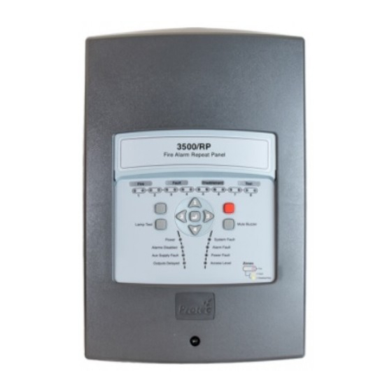
Page 15: Connecting The 3500 Repeat Panel
When carrying out commissioning of the 3500 control panel ensure that the 3500 repeat panels mimic the display of the 3500. Ensure that if the if the repeat panel is locally muted, the buzzer resounds upon the activation of an additional fault or fire. -
Page 16: Connecting The Mains Cabling
‘OFF’ position. Pay particular attention that the incoming mains cable is segregated from all other cables within the 3500 enclosure. Ensure the incoming earth cable is firmly connected to the Main PCB (see figure 5.9) and the earth cable from the Main PCB is securely connected to the brass earth terminals within the back-box. -
Page 17: Connecting The Fire Brigade Panel Controller
5.14 Connecting the Fire Brigade Panel Controller If the 3500 is equipped with the optional fire brigade controller ensure that the ribbon cable and earth lead are re-connected to the rear of the controller as shown in figure 5.11. -
Page 18: Commissioning The 3500
Access Levels Access Level 1 (User code not entered) The panel’s front panel display indicators are visible, providing a clear status of the 3500 at that time. The functions that may be performed at access level 1 are: Entry of the 6 digit user code to access level 2 or level 3 functions •... - Page 19 Access Level 4 (3500 cover removed, tool required) Configuration of global fire relay contact state (normally closed or normally open) • • Configuration of global fault relay contact state (normally closed or normally open) Configuration of alarm output activation type •...
-
Page 20: Programming Zone And Alarm Disablements
Zone test indicators extinguish Testing the Panel Indications and Internal Buzzer The 3500 allows the front panel indications and internal buzzer to be tested. In this mode all indicators are momentarily illuminated and the internal buzzer sounded. If any indicators fail to illuminate, or the buzzer does not sound, note this in the system log and get the fault rectified immediately. -
Page 21: Clearing System Faults
Clearing System Faults In general faults on the 3500 are non-latching and will clear automatically when the fault is rectified. Some faults however are latched on the system and require clearing manually. Sequence Effect Enter the access level 2 code... -
Page 22: Disabling The Internal Buzzer
‘Disablement’ indicator illuminates if buzzer is disabled between buzzer disabled / enabled Programming the Alarm Activation Type The alarm outputs of the 3500 can be configured to turn on continuously, or pulse, when the 3500 is activated. The alarm activation type is configured as follows. Sequence... -
Page 23: Setting Zones Into Test Mode
The 3500 permits zones to be programmed into walk test mode. Activations from zones in walk test mode activate the alarm outputs for 10 seconds, after which the 3500 automatically resets. Activations from a zone not in test mode will operate as normal. -
Page 24: Setting Zones Into Coincidence (Double Knock) Operation
If only one zone in the coincidence group triggers, the 3500 will flash the relevant zone fire indicator, sound the internal buzzer and activate the global fire contacts. The user may then investigate the cause of the alarm and manually activate the alarms in necessary. -
Page 25: Configuring The Volt Free Contact Normal State
6.12 Configuring the Volt Free Contact Normal State The quiescent state of the 3500 Volt free contacts may be configured to be 'Normally Open' or 'Normally Closed'. Table 6.0 shows how setting the configuration links changes the operation. The Volt free contact configuration is setup by setting the front panel configuration links as follows. -
Page 26: 3500 Technical Specification
Output Voltage 24 – 29V dc with mains present , 17 – 29V dc on batteries Deep Discharge Protection Yes. Less than 150µA drawn from batteries (3500 is turned off) Deep Discharge Activation Level 18.5V dc battery terminal Voltage Output Ripple Voltage 400mV maximum (peak to peak) at full output load 27.3V at 20 degrees C. - Page 27 Must be fitted with a series resistor (150 to 680 ). Manual Call Point requirements A 180 ±5% ¼W resistor must be fitted for the 3500 to distinguish between manual and automatic triggers on zones. Alarm circuit specifications Number of alarm circuits...
-
Page 28: Appendix 1 List Of 3500 Spares And Accessories
N 93-571-87 3500 Installation & commissioning manual (this manual) N 93-586-84 Appendix 2 3500 Controls, Indications and Connections The diagram below shows the 3500 Control PCB housing and highlights the main connections and controls. Detection zones Global fire Monitored Monitored... - Page 29 N93-586-84 Issue 04 AB Page 29 of 32 © Protec Fire Detection plc 2015 www.acornfiresecurity.com...
- Page 30 N93-586-84 Issue 04 AB Page 30 of 32 © Protec Fire Detection plc 2015 www.acornfiresecurity.com...
- Page 31 N93-586-84 Issue 04 AB Page 31 of 32 © Protec Fire Detection plc 2015 www.acornfiresecurity.com...
- Page 32 N93-586-84 Issue 04 AB Page 32 of 32 © Protec Fire Detection plc 2015 www.acornfiresecurity.com...
Need help?
Do you have a question about the 3500 and is the answer not in the manual?
Questions and answers