Table of Contents

Subscribe to Our Youtube Channel
Related Manuals for Samson 45-1


Summary of Contents for Samson 45-1
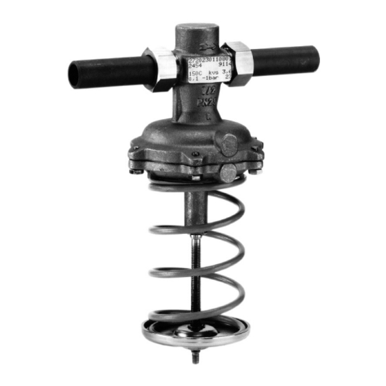
- Page 1 EB 3124 EN Translation of original instructions Type 45-1 Type 45-2 Differential Pressure Regulators Type 45-1 · Type 45-2 · Type 45-3 · Type 45-4 Self-operated regulators · Installation in the flow or return flow pipe Edition April 2022...
- Page 2 Note on these mounting and operating instructions These mounting and operating instructions assist you in mounting and operating the device safely. The instructions are binding for handling SAMSON devices. The images shown in these instructions are for illustration purposes only. The actual product may vary.
-
Page 3: Table Of Contents
Contents Safety instructions and measures ..............1-1 Notes on possible severe personal injury ............1-4 Notes on possible personal injury ..............1-5 Notes on possible property damage .............1-7 Markings on the device ................2-1 Nameplate ....................2-1 Location of the nameplates ................2-1 Material identification number ..............2-2 Design and principle of operation ...............3-1 Additional fittings ..................3-3 3.1.1... - Page 4 Removal ....................11-1 11.1 Removing the regulator from the pipeline ............11-1 11.2 Removing the actuator from the valve ............11-1 Repairs ....................12-1 12.1 Returning devices to SAMSON ..............12-1 Disposal ....................13-1 Certificates ....................14-1 Appendix ....................15-1 15.1 Tightening torques ..................15-1 15.2 Accessories/mounting parts ...............15-1 15.3...
-
Page 5: Safety Instructions And Measures
In case operators intend to use the regulators in applications or conditions other than those specified, contact SAMSON. SAMSON does not assume any liability for damage resulting from the failure to use the de- vice for its intended purpose or for damage caused by external forces or any other external factors. - Page 6 Î Check with the plant operator for details on further protective equipment. Revisions and other modifications Revisions, conversions or other modifications of the product are not authorized by SAMSON. They are performed at the user's own risk and may lead to safety hazards, for example. Fur- thermore, the product may no longer meet the requirements for its intended use.
- Page 7 Safety instructions and measures Safety features The Types 45-1, 45-2, 45-3 and 45-4 Regulators do not have any special safety features. When relieved of pressure, the valves are opened by the force of the set point springs. Responsibilities of the operator Operators are responsible for proper use and compliance with the safety regulations.
-
Page 8: Notes On Possible Severe Personal Injury
Safety instructions and measures Referenced documentation The following documents apply in addition to these mounting and operating instructions: − Mounting and operating instructions for e.g. Type 2 N or 2 NI Strainer u EB 1015 − Data sheets for e.g. Type 2 N or 2 NI Strainer u T 1015 − Mounting and operating instructions as well as data sheets for additional fittings (e.g. -
Page 9: Notes On Possible Personal Injury
Safety instructions and measures 1.2 Notes on possible personal injury WARNING Risk of personal injury due to incorrect operation, use or installation as a result of information on the regulator being illegible. Over time, markings, labels and nameplates on the regulator may become covered with dirt or become illegible in some other way. - Page 10 Î Wear protective clothing and safety gloves. Damage to health relating to the REACH regulation. If a SAMSON device contains a substance listed as a substance of very high concern on the candidate list of the REACH regulation, this is indicated on the SAMSON deliv- ery note.
-
Page 11: Notes On Possible Property Damage
Risk of regulator damage due to the use of unsuitable lubricants. The lubricants to be used depend on the regulator material. Unsuitable lubricants may corrode and damage surfaces. Î Only use lubricants approved by SAMSON. When in doubt, consult SAMSON. Risk of leakage and regulator damage due to over- or under-torquing. - Page 12 Î Use suitable inhibitors. The plant operator is responsible for the selection and use of suitable inhibitors. Note SAMSON's After-sales Service can support you concerning lubricant, tightening torques and tools approved by SAMSON. 1-8 EB 3124 EN...
-
Page 13: Markings On The Device
Markings on the device 2 Markings on the device 2.1 Nameplate 1 Material number 2 Model number 3 Date of manufacture coefficient 5 Pressure rating PN 6 Differential pressure set point range in bar 7 Type designation 8 Maximum permissible temperature in °C Fig. 2-1: Nameplate 2.2 Location of the nameplates Location of the... -
Page 14: Material Identification Number
2.3 Material identification number The material designation can be found on the cast body or you can contact SAMSON (the material number is required) to find out which material is used. It is specified on the nameplate in the 'MNo.' field (1). For more details on the nameplate, see Chapter 2.1. -
Page 15: Design And Principle Of Operation
(13) In Type 45-1 and Type 45-3, the set point and the high pressure from the flow pipe is spring (8) installed into the valve determines transferred to the high-pressure chamber of the set point. - Page 16 Seat Plug 3.1 Plug section 3.2 Plug stem 3.3 Plug stopper Diaphragm plate 12 External control line (Types 45-1 and 45-2) Operating diaphragm 13 Borehole in the body (Types 45-3 and 45-4) 6.1 Actuator stem 14 Screws Actuator housing 15 Spring plate...
-
Page 17: Additional Fittings
Design and principle of operation 3.1 Additional fittings Strainer We recommend installing a SAMSON Î See Fig. 3-3 strainer (2) upstream of the valve. It prevents solid particles in the process medium from Pressure gauges damaging the regulator. Install a pressure gauge (3 and 5) at suitable Î... -
Page 18: Versions
Note Note More information is available in Data Sheet The Types 45-1, 45-2, 45-3 and 45-4 Regu- u T 3124. lators are not safety valves. If necessary, a suitable overpressure protection must be in- Conformity stalled on site in the plant section. - Page 19 Nevertheless, glycol reacts when it comes in- to contact with metals and causes acids to Note form. We cannot prevent this reaction. The Types 45-1, 45-2, 45-3 and 45-4 Regu- Therefore, prevent it through the use of suit- lators are not safety valves. able inhibitors.
- Page 20 0.55 0.45 value Flanged body – 0.45 0.40 Types 45-2 and 45-4 PN 25 Pressure rating Types 45-1 and 45-3 PN 16 · PN 25 PN 25 Max. permissible differential pressure ∆p 20 bar/10 bar 16 bar 2) across the regulator Max. permissible temperature Liquids: 150 °C/130 °C · Air and nitrogen: 150 °C ...
- Page 21 Additional version: regulator with flanged body Table 3-4: Regulator with connecting parts Nominal size DN 15 DN 20 DN 25 DN 32 DN 40 DN 50 With welding ends Type 45-2 · Type 45-4 Weight, approx. kg Type 45-1 · Type 45-3 With threaded ends Male thread A G ½ G ¾ G 1 G 1¼ G 1½ G 2 Type 45-2 · Type 45-4 Weight, approx. kg Type 45-1 · Type 45-3 With flanged valve body (DN 32 to 50)
- Page 22 Type 45-1 and Type 45- 3 · DN 15 to 50 · With welding ends ØD Types 45-1, 45-2, 45-3 and 45-4 · DN 15 Flanged valve body DN 32 to 50 to 50 · With threaded ends Fig. 3-4: Dimensional drawings 3-8...
-
Page 23: Shipment And On-Site Transport
Shipment and on-site transport 4 Shipment and on-site trans- Î Do not remove the protective caps from the inlet and outlet until immediately be- port fore installing the regulator with flanges The work described in this chapter is to be into the pipeline. They prevent foreign performed only by personnel appropriately particles from entering the valve. -
Page 24: Storing The Regulator
Î Observe the storage instructions. Î Store elastomers away from lubricants, Î Avoid long storage times. chemicals, solutions and fuels. Î Contact SAMSON in case of different − We recommend a storage temperature of storage conditions or longer storage 15 °C for elastomers. -
Page 25: Installation
Î Contact SAMSON if the mounting posi- tion. tion is not as specified above. Pipeline routing... -
Page 26: Preparation For Installation
Standard mounting position, installing a needle valve in the control line in suspended addition to the standard SAMSON screw All versions joint with restriction. The standard SAMSON − Air, gases and liquids: max. -
Page 27: Cleaning The Pipeline
Installation 5.2.1 Cleaning the pipeline or prepared as necessary before install- ing the valve. We recommend additionally flushing the Proceed as follows: pipeline without an installed regulator over a Î Lay out the necessary material and tools time period of several minutes before start- to have them ready during installation up. - Page 28 Correct Connection at the top – incorrect position Connection at the side – optimal Connection at the bottom – incorrect position Fig. 5-2: Control line connection, depending on how the pipeline is routed Type 45-1 and Type 45-2 in the flow pipe Type 45-3 and Type 45-4 in the return flow pipe – – Shut-off valve Pressure gauge (flow...
-
Page 29: Installation
Installation 5.3 Installation 5.3.1 Installing the regulator The SAMSON regulators are delivered as The Type 45-1 and Type 45-2 Regulators are assembled units. The activities listed below installed in the flow pipe and the Type 45-3 are necessary for installation and before and Type 45-4 Regulators are installed in the start-up of the regulator. -
Page 30: Filling The Plant
Installation 5.3.2 Filling the plant WARNING Open the shut-off valves slowly over a time Crush hazard arising from moving parts. period of several minutes preferably starting The regulator contains moving parts (actua- from the upstream pressure side to fill the tor and plug stem), which can injure hands plant (all consumers are open). -
Page 31: Leakage
Risk of valve damage due to a sudden The regulator components are delivered by pressure increase. SAMSON ready for use. To test the regulator − Slowly open the shut-off valves. functioning before start-up or putting back the regulator into operation, perform the fol-... -
Page 32: Insulation
Installation 5.5 Insulation Î Make sure that the regulator is open while filling the plant. To proceed, turn To insulate cold systems, we recommend first the set point adjuster (9) or manual ad- filling the plant and carefully rinsing it. The juster (19) counterclockwise () as far as regulator must not yet be insulated at this it will go. -
Page 33: Start-Up
Start-up 6 Start-up WARNING The work described in this chapter is to be Risk of hearing loss or deafness due to loud performed only by personnel appropriately noise. qualified to carry out such tasks. Noise emission may occur during operation caused by the process medium and the oper- ating conditions. -
Page 34: Start-Up And Putting The Device Back Into Operation
Start-up 6.1 Start-up and putting the 6.2 Starting up the plant device back into operation 1. The plant is filled with the process medi- um (see section 'Filling the plant' in the 1. Depending on the field of application, 'Installation' chapter). allow the regulator to cool down or warm up to reach ambient temperature 2. -
Page 35: Operation
Type 45-2 and Type 45-4 Î Do not start up the regulator until all Regulators. The differential pressure set point parts have been mounted. of the Type 45-1 and Type 45-3 Regulators is determined by the internal set point springs (16). WARNING Î... - Page 36 Operation Procedure for the Type 45-2 and Type 45-4 For regulators with manual adjuster, the set Regulators point spring is installed in the bottom section of the valve body (see Fig. 7-1). The set point See Fig. 7-1 and Fig. 7-2. can be continuously adjusted using the set Adjust the required set point by tensioning point adjuster/manual adjuster according to the set point springs (10) at the set point ad- the value on the scale (see Fig. 7-2).
- Page 37 10 Set point springs 25 Scale reading Value on scale Fig. 7-1: Set point adjuster for differential pres- Fig. 7-2: Differential pressure set point adjusted sure according to the value on the scale Type 45-1 and Type 45-2 in the flow pipe Type 45-3 and Type 45-4 in the return flow pipe – – Shut-off valve Differential pressure Shut-off valve...
-
Page 38: Pressure Conditions In The Plant And At The Regulator
Differential pressure (pressure loss) when the plant is Δp plant completely open in bar Valve flow coefficient in m³/h ∆p ∆p set point ∆p ∆p plant restriction Type 45-1, Type 45-2, Type 45-3 or Type 45-4 Fig. 7-4: Pressure conditions in the plant 7-4 EB 3124 EN... -
Page 39: Malfunctions
Î Remove foreign particles. Foreign particles blocking the plug Î Replace damaged parts. Î Contact SAMSON's After-sales Service. Î Replace the damaged seat and plug. Seat and plug are worn or leak. Î Contact SAMSON's After-sales Service. Differential pressure Î... - Page 40 Î Clean the strainer. Defective operating diaphragm Î Replace damaged diaphragm. Î Check the sizing. Loud noises High flow velocity, cavitation Î Install larger regulator, if necessary. Note Contact SAMSON's After-sales Service for malfunctions not listed in the table. 8-2 EB 3124 EN...
-
Page 41: Emergency Action
3. Rectify those malfunctions that can be remedied following the information given SAMSON's After-sales Service can support in this document. Contact SAMSON's you in drawing up an inspection and test After-sales Service in all other cases. - Page 42 8-4 EB 3124 EN...
-
Page 43: Servicing
Servicing 9 Servicing WARNING The regulator does not require much mainte- Risk of burn injuries due to hot or cold nance. Nevertheless, it is subject to natural components and pipeline. wear, particularly at the seat, plug and oper- Regulator components and the pipeline may ating diaphragm. - Page 44 The regulator was checked by SAMSON unsuitable tools. before it left the factory. Î Only use tools approved by SAMSON − Certain test results certified by SAMSON (see section 'Tools' in the Appendix). lose their validity when the regulator is opened.
- Page 45 Seat Plug 3.1 Plug section 3.2 Plug stem 3.3 Plug stopper Diaphragm plate 12 External control line (Types 45-1 and 45-2) Operating diaphragm 13 Borehole in the body (Types 45-3 and 45-4) 6.1 Actuator stem Actuator housing 14 Screws 15 Spring plate Set point spring (fixed set point) 8.1 Valve spring...
-
Page 46: Service Work Preparations
Servicing 9.1 Service work preparations 9.2 Installing the regulator after service work 1. Lay out the necessary material and tools to have them ready for the service work. Î Put the regulator back into operation (see 2. Put the regulator out of operation (see the 'Start-up' chapter). Make sure the re- the 'Decommissioning' chapter). -
Page 47: Replacing The Seat And Plug
Servicing 9.4 Replacing the seat and Installation plug 1. Insert cleaned or new plug. 2. DN 15 to 25: tighten the guide nipple See Fig. 9-1 and Fig. 9-2. with plug (3.1) using a socket wrench (order no. 1280-3001). Observe the Disassembly specified tightening torques (see section 1. -
Page 48: Exchanging The Operating Diaphragm Unit In The Actuator
Servicing 9.5 Exchanging the operating 8. Clamp the actuator housing (7) with ac- tuator stem (6.1) and set point springs diaphragm unit in the actu- into a vise. ator 9. Unscrew the nut (5) and lift off the top di- See Fig. 9-1 and Fig. 9-2. aphragm plate (4). -
Page 49: Version With Manual Adjuster
Servicing 9.5.2 Version with manual ad- Installation juster 1. Slide the new assembly over the spindle (18) into the actuator housing. Disassembly 2. Turn the assembly clockwise () by one 1. Put the regulator out of operation (see turn to screw it onto the spindle (18). the 'Decommissioning' chapter). -
Page 50: Ordering Spare Parts And Operating Supplies
Servicing 9.6 Ordering spare parts and operating supplies Contact your nearest SAMSON subsidiary or SAMSON's After-sales Service for infor- mation on spare parts, lubricants and tools. Spare parts See Appendix for details on spare parts. Lubricants Contact SAMSON's After-sales Service for more information on lubricants. -
Page 51: Decommissioning
Decommissioning 10 Decommissioning WARNING The work described in this chapter is to be Risk of personal injury due to pressurized performed only by personnel appropriately components and as a result of process qualified to carry out such tasks. medium being discharged. Incorrect opening of pressure equipment or mounting parts may lead to the process DANGER... - Page 52 Decommissioning WARNING WARNING Risk of personal injury due to residual process medium in the regulator. While working on the regulator, residual process medium can escape and, depending on its properties, may lead to personal in- jury, e.g. (chemical) burns. Î Wear protective clothing, safety gloves and eye protection.
-
Page 53: Removal
Removal 11 Removal 11.1 Removing the regulator from the pipeline The work described in this chapter is to be performed only by personnel appropriately 1. Support the regulator to hold it in place qualified to carry out such tasks. when separated from the pipeline (see the 'Shipment and on-site transport' WARNING chapter). - Page 54 11-2 EB 3124 EN...
-
Page 55: Repairs
3. Attach the RMA (together with the Decla- service or repair work. ration on Decontamination) to the out- Î Contact SAMSON's After-sales Service side of your shipment so that the docu- for service and repair work. ments are clearly visible. - Page 56 12-2 EB 3124 EN...
-
Page 57: Disposal
Disposal 13 Disposal SAMSON is a producer registered at the following European institution u https:// www.ewrn.org/national- registers/national-registers. WEEE reg. no.: DE 62194439/FR 025665 Î Observe local, national and internation- al refuse regulations. Î Do not dispose of components, lubricants and hazardous substances together with your other household waste. - Page 58 13-2 EB 3124 EN...
-
Page 59: Certificates
Certificates 14 Certificates The EU declarations of conformity are in- cluded on the next pages: − EU declaration of conformity in compli- ance with Pressure Equipment Directive 2014/68/EU on page 14-2. EB 3124 EN 14-1... - Page 60 Typ 2336, 2373, 2375, 44-1B, 44-2, 44-3, 44-4, 44-6B, 44-9, 45-1, 45-2, 45-3, 45-4, 45-6, (Erz.-Nr. 2720), 45-9, 47-4, 2488, 2489, (2730), 2405, 2406, 2421 (2811), 2412 (2812), 2417 (2817), 2422 (2814), 2423 (2823), 2423E (2823) die Konformität mit nachfolgender Anforderung/the conformity with the following requirement...
- Page 61 2333 (Erz.-Nr./Model No. 2333), 2334 (2334), 2335 (2335), 2336, 2373, 2375, 44-0B, 44-1B, 44-2, 44-3, 44-6B, 44-7, 44-8, 45-1, 45-2, 45-3, 45-4, 45-5, 45-6, 2468, 2478 (2720), 45-9, 46-5, 46-6, 46-7, 46-9, 47-1, 47-4, 47-5, 47-9, 2487, 2488, 2489, 2491, 2494, 2495 (2730), 2405, 2406, 2421 (2811), 2392, 2412 (2812), 2114 (2814), 2417 (2817), 2422 (2814), 2423 (2823) die Konformität mit nachfolgender Anforderung/the conformity with the following requirement.
- Page 62 14-4 EB 3124 EN...
-
Page 63: Appendix
1400-6503 1400-6504 1400-6505 1400-6512 1400-6513 1400-6514 1) Gasket 8413-3000 8413-3001 8413-3002 8413-3003 8413-3004 8413-3005 Pair including flat gasket 15.3 Lubricants SAMSON's After-sales Service can support you concerning lubricants and sealants ap- proved by SAMSON. 15.4 Tools SAMSON's After-sales Service can support you concerning tools approved by SAMSON. -
Page 64: Spare Parts
Screw Set point adjuster 134, 135 O-ring Hex nut 137…139 Seal Differential pressure spring Plain bearing 70, 71 Set point springs Axial needle bearing Diaphragm plate Diaphragm Spring plate Fig. 15-1: T ype 45-1 Regulator, DN 15 to 50 15-2 EB 3124 EN... - Page 65 Appendix 31...34 134,135 124, 125 137, 138 70, 71 Fig. 15-2: T ype 45-2 Regulator, DN 15 to 50 EB 3124 EN 15-3...
- Page 66 Appendix Legend for Fig. 15-3 and Fig. 15-4 Plug Shim Diaphragm stem 110, 112 Diaphragm case Body 124, 125 Diaphragm 31…34 Seat Screw Set point adjuster 134, 135 O-ring Hex nut 137…139 Seal Differential pressure spring Plain bearing 70, 71 Set point springs Axial needle bearing Diaphragm plate Diaphragm Spring plate...
- Page 67 Appendix 31 … 34 134, 135 137, 138 70, 71 Fig. 15-4: T ype 45-4 Regulator, DN 15 to 50 EB 3124 EN 15-5...
-
Page 68: After-Sales Service
E-mail address You can reach our after-sales service at aftersalesservice@samsongroup.com. Addresses of SAMSON AG and its subsid- iaries The addresses of SAMSON, its subsidiaries, representatives and service facilities worldwide can be found on our website (u www.samsongroup.com) or in all SAMSON product catalogs. Required specifications Please submit the following details: −... - Page 72 EB 3124 EN SAMSON AKTIENGESELLSCHAFT Weismüllerstraße 3 · 60314 Frankfurt am Main, Germany Phone: +49 69 4009-0 · Fax: +49 69 4009-1507 samson@samsongroup.com · www.samsongroup.com...
Need help?
Do you have a question about the 45-1 and is the answer not in the manual?
Questions and answers