Samson 41-23 Mounting And Operating Instructions
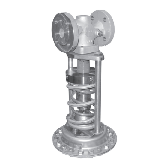
Universal pressure reducing valve
Hide thumbs
Also See for 41-23:
- Mounting and operation instructions (84 pages) ,
- Mounting and operating instructions (78 pages) ,
- Mounting and operating instructions (68 pages)

Related Manuals for Samson 41-23


Summary of Contents for Samson 41-23
- Page 1 Self-operated Pressure Regulators Type 41-23 Universal Pressure Reducing Valve Type 41-23 Pressure Reducing Valve Mounting and Operating Instructions EB 2512 EN Edition March 2016...
- Page 2 The instructions are binding for handling SAMSON devices. Î For the safe and proper use of these instructions, read them carefully and keep them for later reference. Î If you have any questions about these instructions, contact SAMSON‘s After-sales Service Department (aftersalesservice@samson.de). Definition of signal words...
-
Page 3: Table Of Contents
Contents General safety instructions ................4 Process medium and scope of application ............5 Transportation and storage ................5 Design and principle of operation ..............5 Installation ....................6 Assembly ......................6 Mounting position ..................8 Control line, compensation chamber and needle valve ........9 4.4 Strainer (filter)....................10 Shut-off valve ....................10 Pressure gauge ....................10 Operation ....................11 Start-up .......................11... -
Page 4: General Safety Instructions
General safety instructions 1 General safety instructions − The regulator is to be mounted, started up or serviced by fully trained and qualified personnel only; the accepted industry codes and practices are to be observed. Make sure employees or third persons are not exposed to any danger. − All safety instructions and warnings given in these mounting and operating instructions, particularly those concerning installation, start-up and mainte- nance, must be strictly observed. -
Page 5: Process Medium And Scope Of Application
Nominal pressure PN 16 to 40 · Suitable for liquids, gases and vapors up to 350 °C The valve closes when the downstream pressure rises. NOTICE The Type 41-23 Pressure Reducing Valve is not a safety valve. If necessary, a suitable overpressure protection must be installed on site in the plant section. 2.1 Transportation and storage The regulator must be carefully handled, transported and stored. -
Page 6: Installation
Installation lows (12.1). The positioning force is used to and fasten with nuts (width across flats 24, 8.2) to the actuator (max. 60 Nm). move the valve plug according to the force of the positioning springs (7). The spring force For metal bellows actuators in DN 65 to is adjustable at the set point adjuster (6). 100, remove the crossbeam (8) from the 4 and higher feature a bal- Valves with K valve and unscrew the pillars (8.1). Screw ancing bellows (4). The upstream pressure the pillars into the threaded holes (8.3) of the acts on the outside of the bellows and the actuator flange as far as they will go. Push downstream pressure on the inside of the the actuator with actuator stem (11) onto the bellows. - Page 7 Diaphragm Actuator (25 Nm) (40 Nm) DN 65 to 100 Table 1: Assignment of compensation chamber (18) to regulator Item 14: Apply Loctite 272 sealant (SAMSON order no. 8121-4000) to ∙ Item number Compensation chamber Actuator area A in the bottom section of thread on the cm² DN 15 to 50 DN 65 to 250...
-
Page 8: Mounting Position
NOTICE On request: Permissible for regulators with fixed plug stem guide Install a strainer (e.g. SAMSON plus with medium temperature up to Type 2) upstream of the regulator. 80 °C. Not for steam. Fig. 2: Mounting position Install the pressure reducing valve in hori- zontal pipelines. -
Page 9: Control Line, Compensation Chamber And Needle Valve
Connect the control line to the downstream ping pressure directly at the valve body is ) at least one meter away from the line (p available as an accessories part from valve outlet (Fig. 3.1). If a manifold is locat- SAMSON. ed downstream of the pressure reducing Compensation chamber ∙ See Table 1 on valve (Fig. 3.2), connect the valve to the page 7. A compensation chamber is re- manifold, even if it is several meters away. If quired for liquids above 150 °C as well as... -
Page 10: Strainer (Filter)
(not between the tapping point and the the standard SAMSON screw joint with re- valve). striction. EB 2512 EN... -
Page 11: Operation
Operation 5 Operation Make sure that the pressure rises si- multaneously upstream and down- 5.1 Start-up stream of the regulator to avoid dam- aging the balancing bellows. See Fig. 1 on page 7. Do not exceed the maximum permis- Cleaning the pipeline sible pressure (1.5 times the nominal pressure of the valve body). -
Page 12: Decommissioning
Operation Table 2: Set point adjustment – Dimension x The pressure gauge located on the down- Set point stream pressure side allows the adjusted set Nominal size DN range point to be monitored. 8 to 16 bar 15 to 25 32 to 50 65 to 100 An adjustment of the set point can also be 10 bar... -
Page 13: Cleaning And Maintenance
We recommend max. tightening torque of 40 Nm. During as- removing the valve from the pipeline. sembly, apply Loctite 272 sealant (SAMSON When used at high temperatures, al- order no. 8121-4000) to the bottom section low the plant section to cool down to of thread on the actuator stem during assem- ambient temperature. - Page 14 Cleaning and maintenance Table 3: Troubleshooting Malfunction Possible reasons Recommended action Insufficient pressure pulses on the op- Clean the control line and the screw joint with re- erating diaphragm. striction. Seat and plug worn down by deposits Disassemble the regulator and replace damaged or foreign particles. parts.
-
Page 15: Customer Inquiries
Contact SAMSON's After-sales Service department for support when malfunctions or defects arise. E-mail address: aftersalesservice@samson.de The addresses of SAMSON AG, its subsidiaries, representatives and service facilities world- wide can be found on the SAMSON website (u www.samson.de), in all SAMSON product catalogs or on the back of these Mounting and Operating Instructions. - Page 16 Customer inquiries Table 4: Dimensions in mm and weights Pressure reducing valve Type 41-23 Valve size Length L Height H1 Forged steel – – – – Height H3 Other materials Standard version with rolling diaphragm Height H 0.05 to 0.25 bar ØD = 380 mm, A = 640 cm² Actuator Height H 0.1 to...
-
Page 17: Nameplate
Nameplate 9 Nameplate Nameplates are attached to the valve and the actuator. DIN version Valve nameplate Valve type Model number with index Configuration ID (Var.-ID) Order number or date coefficient DIN version Spring force Valve size Nominal pressure Perm. differential pressure Perm. temperature Body material ANSI version ANSI version... -
Page 18: Technical Data
Technical data 10 Technical data Table 5: Technical data · All pressures in bar (gauge) Valve Type 2412 PN 16, 25 or 40 Nominal pressure DN 15 to 50 DN 65 to 80 DN 100 Nominal size 16 bar Max. permissible differential 25 bar 20 bar pressure ∆p Max. permissible See pressure-temperature diagram in u T 2500 temperature Metal seal: max. 350 °C · PTFE soft seal: max. 220 °C · EPDM or FPM Valve plug soft seal: max. 150 °C · NBR soft seal: max. 80 °C Metal seal: leakage class I (≤0.05 % of K... - Page 19 Note: Conversion from chromate coating to iridescent passivation We at SAMSON are converting the surface treatment of passivated steel parts in our production. As a result, you may receive a device assembled from parts that have been subjected to different surface treatment methods. This means that the surfaces of some parts show different reflections.
- Page 20 SAMSON AG · MESS- UND REGELTECHNIK Weismüllerstraße 3 · 60314 Frankfurt am Main, Germany Phone: +49 69 4009-0 · Fax: +49 69 4009-1507 EB 2512 EN samson@samson.de · www.samson.de...
Need help?
Do you have a question about the 41-23 and is the answer not in the manual?
Questions and answers