
Subscribe to Our Youtube Channel
Related Manuals for Teledyne Kuro


Summary of Contents for Teledyne Kuro
- Page 1 Kuro™ sCMOS Camera System Manual 4411-0159 Issue 2 March 28, 2019 www.princetoninstruments.com...
- Page 2 TEL: 800-874-9789 / 609-587-9797 FAX: 609-587-1970 No part of this publication may be reproduced by any means without the written permission of Teledyne Princeton Instruments. Printed in the United States of America. Pentium is a registered trademark of Intel Corporation.
-
Page 3: Table Of Contents
Kuro Camera and System Maintenance ........ - Page 4 Connect Kuro to the PCIe Bus ........
- Page 5 Kuro Rear Panel Connectors ........13...
- Page 6 Kuro sCMOS Camera System Manual Issue 2 This page is intentionally blank.
-
Page 7: About This Manual
Quick Start Guide Kuro sCMOS Camera Teledyne Princeton Instruments maintains updated documentation and user manuals on their FTP site. Visit the Teledyne Princeton Instruments FTP Site to verify that the most recent user manual is available and being referenced: ftp://ftp.piacton.com/Public/Manuals/Princeton Instruments... -
Page 8: Document Organization
This chapter provides information about the installation of Teledyne Princeton Instruments’ LightField image acquisition software. • Chapter 4, System Installation This chapter provides information about for connecting the Kuro camera to the host computer using the USB3.0 bus. • Chapter 5, Theory of Operation This chapter provides an overview of sCMOS camera technology as used in the Kuro camera. -
Page 9: Minimum Host Computer Specifications
Chapter 1 About this Manual Minimum Host Computer Specifications The minimum host computer specifications are: ® • Windows 7/8/10 (64-bit) • 2 GHz or faster Intel processor: either Xeon or Core i7 • 8 GB RAM (or greater) • CD-ROM drive •... -
Page 10: Kuro Safety Information
• Do not operate the camera without cooling (air or liquid.) • Never open the camera. There are no user-serviceable parts inside the Kuro camera. Opening the camera voids the warranty. • Use only the PCI Express interface card, cables and power supply designated for this camera system. -
Page 11: Kuro Camera System
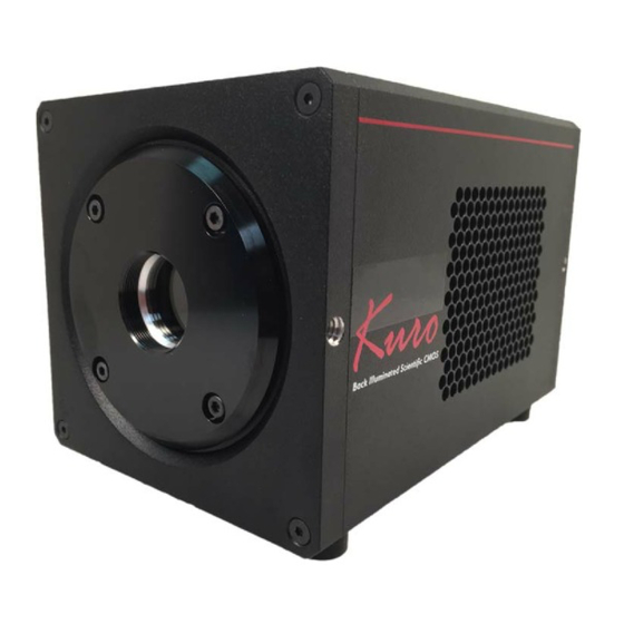
CMOS (sCMOS) camera system to implement back-illuminated sensor technology with powerful software. Capable of very low read noise, >95% QE, and >82 fps at full 1200 x 1200 resolution, Kuro is ideal for many challenging lowlight applications. Figure 2-1:... - Page 12 • High Speed and Low Read Noise Kuro offers very high frame rates, up to 41 fps (16 bit) or 82 fps (12 bit) at full 1200 x 1200 resolution with an exceptionally low 1.3 e rms (median) read noise.
-
Page 13: Connectors And Indicators
Chapter 2 Kuro Camera System 2.1.1 Connectors and Indicators Figure 2-2 illustrates the connectors and indicators on a Kuro camera. Figure 2-2: Kuro Rear Panel Connectors DC IN TRIGGER 12V 10A USB 3.0 DATA Refer to Table 2-1 for information about each rear-panel connector. -
Page 14: Application Software
Kuro sCMOS Camera System Manual Issue 2 Application Software Teledyne Princeton Instruments offers a number of data acquisition software packages for use with Kuro camera systems, including: ® • LightField The Kuro camera can be operated using LightField, Teledyne Princeton ®... -
Page 15: Accessories
2.3.1 Microscopes, Lenses, and Tripods The Kuro camera includes a standard threaded video mount and can be mounted to any microscope that accepts a standard C-mount adapter. The Kuro camera accepts any lens that is compatible with a standard threaded video mount as long as its optics do not extend behind the flange of the lens. -
Page 16: Kuro Camera And System Maintenance
2.5.1 Camera Although there is no periodic maintenance that needs to be performed on a Kuro camera, users are advised to wipe it down with a clean, dry, lint-free cloth from time to time. This should only be done on the external surfaces and when all covers are in place and secured. -
Page 17: Install Lightfield
Insert the LightField Installation CD into the CD drive on the host computer, and follow the on-screen prompts. 2. After the installation has been completed, reboot the host computer. 3. Connect the Kuro system components to the host computer and apply power. 4. Launch LightField, activate it, and begin experiment configuration. - Page 18 Kuro sCMOS Camera System Manual Issue 2 This page is intentionally blank.
-
Page 19: System Installation
This chapter provides information about the installation of hardware for a Kuro system. Connect Kuro with USB 3.0 Kuro’s USB3.0 interface is ubiquitous and easy to use. To use the interface, the PC must have an open USB3.0 port. Kuro is not USB2.0 compatible. USB3.0 ports are usually indicated by the SuperSpeed+ logo and are typically blue in color. - Page 20 Kuro sCMOS Camera System Manual Issue 2 With the cable connected on both ends, the computer can be powered on: With the camera off, connect the USB3.0 cable between camera and host computer. 2. Power the camera on. 3. Wait 30 seconds before launching the application. An LED on the rear of the camera...
-
Page 21: Theory Of Operation
Of course, there are many challenges to obtaining the same analog performance from each of the Kuro's 1.4 million pixels, whereas a CCD has a single, common output node resulting in a uniform response. The most common problems are pixel-to-pixel non-uniformity in gain and offset, Random Telegraph Noise (RTN,) and defective pixels with abnormal noise or dark current characteristics (i.e., hot pixels.) -
Page 22: Gain Combining
(The row being digitized “rolls” through the sensor.) For Kuro, the time to digitize a single row is 20 s, and consequently the delay between the start of exposure between two adjacent rows is approximately 9.6 s. -
Page 23: Bias Offset
NOTE: The specific Bias Offset value for each Kuro camera is programmed at the factory and is not user-configurable. A typical Bias Offset value is approximately 100 counts. - Page 24 Kuro sCMOS Camera System Manual Issue 2 This page is intentionally blank.
-
Page 25: Operating Features
However, it provides lower frame rates than can be achieved with 12-bit mode. Region of Interest Kuro supports the creation of a single Region of Interest (ROI.) An ROI is an image subregion selected by the user to be captured and delivered to the host PC in place of the full image. -
Page 26: Mounting Kuro To A Spectrograph
(i.e., all available columns,) but reduces the number of rows being read out. With Kuro, since the CCD is rotated by 90°, when defining an ROI, it is important to realize that rows and columns are now transposed: •... -
Page 27: Device Synchronization (Triggering)
Chapter 6 Operating Features Device Synchronization (Triggering) Kuro offers several methods of integrating with external hardware devices. Each camera includes a 10-pin, Hirose HR212-10RC-10SDL(74) connector on the back of the camera for trigger input/output operations. Refer to Table 6-1 for pinout information. -
Page 28: Trigger Modes
All triggers are rising edge triggers. • No Response This is the default triggering mode for Kuro. When No Response is selected, incoming trigger pulses are ignored. This mode is typically used for experiments incorporating a constant light source (e.g., a CW laser, DC lamp.) Other experiments that can use this mode are high... -
Page 29: Rolling Shutter Readout
Chapter 6 Operating Features Rolling Shutter Readout NOTE: All timing diagrams incorporate rising edge triggers. The Expose Out I/O signal goes high only when all rows within a single frame are being exposed simultaneously. The length of the Expose Out signal is equal to the time between the start of the last row's exposure and the end of the first row's exposure. -
Page 30: Fan Speed Control And Liquid Cooling
However, under demanding conditions, fan vibration isolation is insufficient for single molecule localization, high magnification imaging, or use with micro-manipulators. Kuro solves this problem in two ways. First, a new, innovate fan mounting system has been developed that isolates fan vibration from the rest of the camera. Side-by-side testing with competing products indicate that Kuro outperforms competitors in terms of vibration isolation. -
Page 31: Appendix A: Technical Specifications
CAUTION! All specifications are subject to change. This appendix provides some technical information and specifications for Kuro cameras. Additional information may be found on data sheets available on the Teledyne Princeton Instruments website (www.princetoninstruments.com). Camera Weight Weight: 3.8 lbs. (1.7 kg) -
Page 32: Liquid Circulator Connector Information
4 ft [1.22 m] Certifications CE, UL, CUL, FCC, PSE Efficiency level VI NOTE: CE certification applies to the Kuro camera only when the camera system operates with a CE-approved power supply. Figure A-1: Typical Power Supply Liquid Circulator Connector Information •... -
Page 33: Appendix B: Outline Drawings
Appendix B: Outline Drawings This appendix provides outline drawings for the Kuro camera. NOTE: All measurements are in inches [millimeters]. Figure B-1: Outline Drawing: Kuro Front View... - Page 34 Kuro sCMOS Camera System Manual Issue 2 This page is intentionally blank.
-
Page 35: Appendix C: Liquid Cooling Setup
Coolant Coolant Hoses Coolant Perform the following procedure to configure the Kuro system for liquid cooling: Unpack the cooler and hose assembly. 2. Confirm the cooler and hoses are pre-filled with blue-colored coolant. 3. Press one hose connector into its mate on the cooler. - Page 36 Kuro sCMOS Camera System Manual Issue 2 9. Plug-in the cooler and turn it on. 10. Look through the clear cover on the coolant reservoir to observe the liquid level and confirm circulation. NOTE: The liquid surface will appear agitated with normal circulation.
-
Page 37: Appendix D: Troubleshooting
Make sure the new interface card is inserted in an expansion slot according to the computer manufacturer's instructions. 2. Ensure Kuro is connected and powered on at least 10 seconds before starting the computer when using the PCIe interface. 3. When using the USB3.0 interface, wait for the LED on the rear of the camera to stop blinking before checking for “New Hardware Found”... -
Page 38: Camera Running Too Warm
However, if it is more than slightly warm to the touch (and at least one inch of space has been left around the external cooling fins for airflow,) switch off the camera immediately and contact Teledyne Princeton Instruments Customer Service. Refer to Contact Information on page 46 for complete information. -
Page 39: Appendix E: Pci Express (Pcie) Card
Install the PCI Express (PCIe) Card Figure E-1 illustrates a typical PCIe interface card. NOTE: The specific PCIe card shipped with the Kuro may vary from that illustrated. Figure E-1: Typical PCI Express Interface Card Perform the following procedure to install a PCIe card into the host computer: Shut down the host computer and unplug it from the wall receptacle. -
Page 40: Connect Kuro To The Pcie Bus
E-3. Figure E-3: Typical Motherboard PCIe Slots 4. Holding the Kuro PCIe card and being careful not to touch the board’s components or PCIe bridge pins insert it with the proper orientation into the open slot. The card should slide into place with minimal resistance and snap when fully inserted. -
Page 41: Troubleshooting
4. Switch on the camera (power switch on the side of camera.) 5. Wait 10 seconds before powering on the PC. NOTE: The power supply and connector used by the Kuro sCMOS camera is a common type. However, Teledyne Princeton Instruments carefully selects power supplies for optimum noise performance, EMI compliance and stability. - Page 42 Kuro sCMOS Camera System Manual Issue 2 This page is intentionally blank.
-
Page 43: Warranty And Service
(1) year after shipment. During this period, Teledyne Princeton Instruments will repair the product or, at its sole option, repair or replace any defective part without charge to you. You must deliver the entire product to the Teledyne Princeton Instruments factory or, at our option, to a factory-authorized service center. -
Page 44: Sealed Chamber Integrity Limited 12 Month Warranty
(1) year from shipment. Teledyne Princeton Instruments does not warrant that the function of the software will meet your requirements or that operation will be uninterrupted or error free. -
Page 45: Owner's Manual And Troubleshooting
3. All warranty service must be made by the Teledyne Princeton Instruments factory or, at our option, an authorized service center. 4. Before products or parts can be returned for service you must contact the Teledyne Princeton Instruments factory and receive a return authorization number (RMA.) Products or parts returned for service without a return authorization evidenced by an RMA will be sent back freight collect. -
Page 46: Contact Information
In no event shall Teledyne Princeton Instruments’ liability exceed the cost of the repair or replacement of the defective product or part. - Page 47 This page is intentionally blank.
- Page 48 info@princetoninstruments.com USA +1 877-474-2286 | France +33 (1) 60 86 03 65 | Germany +49 (0) 89 660 7793 | UK & Ireland +44 (0) 1628 472 346 Singapore +65 6408 6240 | China +86 10 659 16460 | Japan +81 (3) 5639 2741...
Need help?
Do you have a question about the Kuro and is the answer not in the manual?
Questions and answers