Advertisement
Quick Links
Safety
Torque Testers
• Calibration weights can cause tester
and its base to tip
Wear safety goggles (users and
bystanders).
Counterbalance or anchor mounting
base.
Tipping base can cause injury.
Sturtevant Richmont
Phones: 847/455-8677 800/877-1347 Fax: 847/455-0347
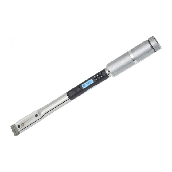
DTC Wrench
Torque Wrenches
• Overtorquing can cause breakage
• Wrench can break while breaking
fasteners loose
• An out-of-calibration torque wrench can
cause part or tool breakage
Wear safety goggles (user and
bystanders).
Do not exceed rated torque.
Do not use a torque wrench to break
fasteners loose.
Periodic recalibration is necessary to
maintain accuracy.
Broken tools can cause injury.
P/N 857421 Rev A - 08/9/19
555 Kimberly Drive Carol Stream, IL 60188
E-mail: CustomerService@srtorque.com
Operating Instructions
Battery Information
NiMH Batteries rated 1400 mAh to 2400
mAh are acceptable. Higher mAh ratings
mean more cycles between recharge and
longer recharge times.
Unlike our other digital torque wrenches,
the DTC can use alkaline, Ni-MH, or
Lithium Ion batteries. Never mix types of
batteries (e.g. never combine alkaline and
Ni-MH batteries, or Ni-MH and Lithium
Ion batteries) and never mix new and old
batteries in the DTC.
Although the DTC uses both alkaline and
rechargeable batteries, we recommend
rechargeable batteries because they are
environmentally friendly.
The DTC uses three AAA batteries in a
reusable cartridge.
URL: srtorque.com
Page 1
Advertisement

Subscribe to Our Youtube Channel
Related Manuals for Sturtevant Richmont DTC


Summary of Contents for Sturtevant Richmont DTC
- Page 1 555 Kimberly Drive Carol Stream, IL 60188 Phones: 847/455-8677 800/877-1347 Fax: 847/455-0347 E-mail: CustomerService@srtorque.com URL: srtorque.com DTC Wrench Operating Instructions Safety Torque Testers Torque Wrenches Battery Information NiMH Batteries rated 1400 mAh to 2400 mAh are acceptable. Higher mAh ratings mean more cycles between recharge and longer recharge times. • Calibration weights can cause tester • Overtorquing can cause breakage Unlike our other digital torque wrenches, and its base to tip the DTC can use alkaline, Ni-MH, or • Wrench can break while breaking Lithium Ion batteries. Never mix types of Wear safety goggles (users and fasteners loose batteries (e.g. never combine alkaline and bystanders). • An out-of-calibration torque wrench can Ni-MH batteries, or Ni-MH and Lithium cause part or tool breakage Counterbalance or anchor mounting Ion batteries) and never mix new and old base.
- Page 2 Backlit LCD graphic display • Displayed Icons: • ! Press ! to increase the displayed value or scroll up # Press # to decrease the displayed value or scroll down $ Press $ to go to next screen in sequence or select the highlighted line Showing target torque and angle, as opposed to actual Clockwise target or current torque direction Counterclockwise target or current torque direction Either target direction Keypad and/or P-Sets are locked Battery charge level Status indicators – LEDs, buzzer, handle vibration • USB connector and cord – Connects to a PC COM port for wrench setup and event logging via • the DTC Connect application. Store 99 parameter settings (P-Sets). • Store over 1000 results. • OPERATING INSTRUCTIONS Power On / Power Off Insert 3 AAA batteries in the battery holder, then insert the holder in the wrench. The wrench • will power up and display: ZEROING ANGLE DO NOT MOVE TOOL (For best results, set the wrench on a hard surface to zero the angle sensor.) Sturtevant Richmont logo. An identification screen displaying the model and firmware version. DTC-75 V2.00 The next screen shown is configuration-dependent.
- Page 3 After about 3 seconds the wrench will show the Idle Screen (see below). To “cold-start” at the SR logo, the battery cap must be backed off far enough to blank the display, then turned fully clockwise. Press " momentarily at any time to go to the Idle Screen. • Press U at any time to change Unit of Measure. • Press P at any time for P-Set selection. • Configuring the Display Complete configuration of the DTC is available via DTC Connect. The simplest configuration shows an Idle Screen after the identification screen, in Peak mode. Apply 4% of full scale torque or more to switch from the Idle Screen to the Measurement • Screen. PEAK 123.4 56.7 The large digits show the target or measured peak torque. • Direction of intended or measured torque is shown. • The Idle Screen will reappear when torque is released after the auto-clear time expires or " is • pressed. This sequence can be repeated indefinitely. • In contrast, the maximum configuration consists of this sequence of screens: Calibration Screen (only after a cold start) • Idle Screen • Mode Screen • Target Torque Screen • Minimum Torque Screen •...
- Page 4 Additional screens can be reached by pressing other keys. For example, pressing #on the Calibration Screen starts a sub-sequence of more screens to work through calibration. Any screen in the sequence can be added to or removed from a wrench configuration using DTC Connect. Units of Torque Press U to change the units of torque measurement at any time. If not currently showing units of torque, press U to show the Idle Screen with the current units • of torque. Once units of torque are displayed (on the Idle Screen or the Target, Minimum, or Maximum • Torque Screen), press U repeatedly as needed to step through all choices of units, with the displayed torque converted to those units. PEAK PEAK 123.4 10.28 Choices are: IN LB, FT LB, C NM, NM, CM KG, and M KG. • General Operation Three phases of operation are repeated for each joint: 1. Idle: showing the measurement mode and target, and waiting for torque; 2. Torque Applied: showing the Measurement Screen; 3. Torque Released: showing the Measurement Screen and waiting to clear. Idle Screen As shown below, the Idle Screen is somewhat different for each mode. Track and Residual modes don’t show target values. The target angle, not torque, is shown for T2A mode. 0° PEAK 123.4 RESIDUAL ° 123.4 Press $ to go to the next screen in sequence. • Page 4...
- Page 5 PEAK TRACK If more than one measurement mode is configured, the Mode Screen should be included in the configuration. The screen lists up to 3 modes at a time. The current mode is highlighted. • Press ! or # to scroll through the list of modes, wrapping around at either end of the list. • Press $ to select the highlighted mode and go to the next screen in the sequence. • Settings Per Mode Some settings have different meanings for different modes. • Some settings are irrelevant in some modes. • When the Idle Screen is showing, press ! or # to display the first settings screen for that • mode. Target Torque Screen TARGET TORQUE 100.0 Press ! or # to increment/decrement by 1 in the rightmost digit. • Press and hold ! or # to accelerate incrementing/decrementing. • At zero, pressing # causes alternation between (clockwise), (counterclockwise) and • (both). Then ! starts incrementing from zero. Page 5 Sturtevant Richmont P/N 857421 Rev A - 08/9/19...
- Page 6 If is shown, torque will accumulate in both directions, e.g., when a wrench is flipped over between small angular swings in a tight location. If or is shown, torque in the wrong direction will light the red LED, but otherwise it will have no effect. This allows loosening a joint before retightening, with nothing logged or reported, only a warning light. Press $ to proceed to the next screen in sequence or " to go home to the Idle Screen. • Torque Tolerances Torque for a joint may be specified with a “plus or minus” tolerance. In practice, this doesn’t always give the desired control over the use of a torque tool. Instead, if torque falls between a minimum and a maximum value, the joint is deemed OK. The DTC can use either strategy since values are stored separately. Target Torque is stored internally as a torque value in a unit of measure, Minimum Torque is stored as a “minus” tolerance percentage, and Maximum Torque is stored as a “plus” tolerance percentage. Once set, if tolerance percentages do not change, only the Target Torque value need be changed from one joint to another. During operation, the tool lights the green LED if a final result is in the minimum to maximum range and red if the maximum is exceeded. The Target Torque screen was added to hold off the green LED until the operator pulled to a chosen value higher than the minimum torque, typically the midpoint of the range. This corresponds to “target plus or minus tolerance”. Minimum Torque Screen MIN TORQUE 3.0% 97.0 When Target Torque is changed, Target Torque minus the low tolerance is the new Minimum • Torque. In the example above, for a target of 100.0 in.lb. and a 3% tolerance, Minimum Torque would initialize to 97.0 in.lb. Use ! or # to increment/decrement Minimum Torque in the same way as Target Torque. The • final value of Minimum Torque determines a new low tolerance, namely (Target minus Minimum) divided by Target. A possible strategy is to set Minimum equal to Target. The new low tolerance will be 0%. Every • subsequent change to Target will change Minimum to match the new Target. Then under- torquing will never get a green light or an OK status. Press $ to proceed to the next screen in sequence or " to go home to the Idle Screen.
- Page 7 • Press $ to proceed to the next screen in sequence or " to go home to the Idle Screen. • Target Angle TARGET ANGLE 40° Press ! or # to increment/decrement by 1 in the rightmost digit. • Press and hold ! or # to accelerate incrementing/decrementing. • The Target Angle Screen does not specify a direction because it is always in the same direction • as torque. Press $ to proceed to the next setting or " to go home to the Idle Screen. • Maximum Angle MAXIMUM ANGLE 9999° Maximum Angle is set like Target Angle. Direction is not specified. When Target Angle is changed, Maximum Angle is also changed to keep the range the same number of degrees. Decrementing stops at Target Angle and incrementing stops at 9999°. • Press $ to proceed to the next setting or " to go home to the Idle Screen. • Page 7 Sturtevant Richmont P/N 857421 Rev A - 08/9/19...
- Page 8 NO CHANGE LOCK PSETS Press ! to lock out keypad changes to any settings. • Press # to make P-Sets read-only (disables the SAVE PSET Screen). • The U key is not disabled by locking the keypad or P-Sets. • When P-Sets are locked, the bottom prompt becomes UNLOCK PSETS. • Press $ to proceed to the next screen in sequence or " to go home to the Idle Screen. • When keypad is locked, a lock icon – – appears in the top line. The Target Torque value cannot be changed. However the 3 phases – Idle, Torque Applied, and Torque Released – operate normally. To unlock either the keypad or P-Sets, a 4-digit password must be entered correctly. When the keypad is locked, press any key to show the UNLOCK PASSWORD Screen. • When P-Sets are locked, press # on the Lock Screen to choose UNLOCK PSETS or press and hold • the P key to save a P-Set. The UNLOCK PASSWORD Screen will be displayed. Log Screen DISABLE LOG SKIP CLEAR LOG Page 8 Sturtevant Richmont P/N 857421 Rev A - 08/9/19...
-
Page 9: Unlock Password
Press # to clear the tool event log. When cleared, logging will restart with sequence number 1. • (Logging sequence numbers continue to 999, then wrap around to 000.) Press $ to leave this screen and return to at the Idle Screen. • Unlock Password Screen UNLOCK PASSWORD UNLOCK PASSWORD 2114 0000 Press ! or # to increment/decrement the highlighted digit by 1, wrapping around upward • from 9 to 0 and downward from 0 to 9. Press $ to move the highlight one digit to the right or, when all 4 digits have been entered, to • verify the password. The factory default password is 2114. It can be changed using DTC Connect. When unlocking the keypad: • If the password is incorrect, the Idle Screen is shown again with the icon . If the password is correct, the Idle Screen is shown without the icon . Save P-Set Screens All settings for one type of joint can be saved as a P-Set. The P-Set can be recalled from the list as needed, instead of reentering all individual settings each time. Press and hold P at any time to save the current mode, torque and angle settings, and head • length as a P-Set. If P-Sets are locked, the UNLOCK PASSWORD screen is displayed. Enter the password as described previously. Press and hold P again to save the settings. Initially no P-Sets are defined. Available P-Set indices are designated “FREE”. - SAVE PSET - P01 - FREE Press ! or # to scroll through the list of P-Sets, wrapping around at either end of the list. After... - Page 10 - SELECT PSET - If no P-Sets have been saved, “NO PSETS FOUND” is displayed. Press " to go back to the Idle Screen. Press ! or # to scroll through the list of P-Sets, wrapping around at either end of the list. After • the initial screen, 3 lines of the list are always displayed in sorted order. (“FREE” P-Sets are not displayed in this list.) Press $ to retrieve all settings for the highlighted P-Set and return to the Idle Screen using • those settings. Press " at any time to escape without retrieving a P-Set. • When a P-Set has been retrieved, the P-Set number appears on the Idle Screen instead of the • icon. As soon as a setting in that P-Set has been changed, the icon replaces the P-Set number on the Idle Screen to denote that the P-Set is no longer in effect. Delete P-Set P-Sets can only be deleted using DTC Connect. When a P-Set is deleted, it is replaced by a Pxx FREE entry in the SAVE PSET list, and no longer appears in the SELECT PSET list. Data Capture Data about each recorded torque event is stored to a log that may be retrieved using DTC Connect. The log contains the following data for each recorded event: Sequence Number, Date, Time, P-Set, Mode, Units, Torque Direction, Final Torque, Residual Torque, Final Angle, Double Hit Angle, Event Status, Torque Status, Angle Status, Target Direction, Target Torque, Minimum Torque, Maximum Torque, Snug Torque, Minimum Angle, Maximum Angle, Tool Serial Number, Tool Name, Tool Model, and Battery Level. More detail on these fields is provided in the Tool Results Log section below. MODES Settings Per Mode The meaning of some settings may change depending on mode. The following are settings relevant to each mode. If a setting is not available through a menu screen on the tool, it may be possible to modify the value using DTC Connect. Track Mode Track mode constantly shows the current torque on the wrench, and the current angle relative to the start of track mode when 4% of full scale torque is applied. Only two settings are used: Minimum Torque – The green LED lights while above this torque and below Maximum Torque.
- Page 11 Target Torque – Pull to this value to get a green LED. • Minimum Torque – Status is OK between minimum and maximum torque. The green LED turns • on when torque is released if peak torque is between minimum and maximum torque. Maximum Torque – The red LED lights and the status is HI if the peak value exceeds this torque. • Yellow Torque – Percent of Minimum Torque at which the third yellow LED lights up. (All three • yellow LEDs light up in equal steps of torque.) The default value is 90%. Ignorable Torque – Percent of Minimum Torque below which a final peak torque is ignored (not • printed and not logged). The default value is 90%. Another likely value to use is 0% (log all events). Residual Mode Residual mode shows zero torque on the wrench until residual torque is detected, then it shows the residual torque until torque is released, with an OK status. Target Angle – The default is 3°. This may be modified through the keypad. To look for the • torque dip only, set the target angle to 0°. Other settings can be tuned as needed using DTC Connect. Two methods may be applied to detect residual torque. On a soft joint, a pull through a small prescribed angle denotes that residual torque has been • reached. The value at that exact angle represents the residual torque that was in the joint. A minimum of 3° is recommended. On a hard joint, a dip in torque may be detected when applied torque breaks the joint loose • momentarily. The value at the bottom of the dip represents the residual torque that was in the joint. Both the residual torque (“as found”) and the final torque (“as left”) are logged. T2A Mode In Torque to Angle mode, a joint is tightened to a prescribed target torque; then the fastener is turned through an additional angle, intended to stretch the fastener and thus apply clamp load by an amount proportional to the angle. As torque is applied, it is displayed in large digits, with an angle of 0°. When the Target Torque is reached, a yellow LED lights and the display changes to angle in the large digits, starting at 0°. As angle approaches its target, the other yellow LEDs light up. Page 11...
- Page 12 TAM mode uses the same settings as Peak mode, plus: Target Angle – This is the minimum angle needed before minimum torque is reached. • CALIBRATION Calibration Screen If configured to display the CALIBRATE WRENCH screen, calibration can be initiated through the keypad during a cold start. The following screen appears after the Identification Screen, and then not again until the next cold start. CALIBRATE WRENCH Press # to enter calibration mode. The Calibration Password screen appears. • Press $ to skip to normal operation. • Calibration Password Screen A 4-digit password must be entered correctly before the wrench can be calibrated. The Calibration Password Screen is analogous to the Unlock Password Screen described • previously. The factory default password is 3112. It can be changed using DTC Connect. If the password is incorrect, the Calibration Screen is redisplayed. If the password is correct, the Calibration Head Length Screen is displayed. Press " to return to the CALIBRATE WRENCH Screen. • Calibration Head Length Screen The calibrator will have the ability to modify the calibration head length from its default value (36.51). CAL HEAD LENGTH 36.51 Page 12 Sturtevant Richmont P/N 857421 Rev A - 08/9/19...
- Page 13 Press $ to enter angle calibration. Press # to set cal date and next cal date. On the next screen: Press $ to accept the date shown and enter angle calibration. Press ! to return to torque calibration. Angle Calibration Screen CAL ANGLE SET 0° DONE 1.23 CCW 180° Place wrench on an angle calibration fixture with handle to the right of the head. • Press the “SET 0° !“ arrow key on wrench to save the 0° value. • Swing the wrench CCW 180°, press the “CCW 180° #” arrow key on the wrench to save the 180° • value. Swing the wrench CW 180°. The angle reading should display 0°. If not, press the “SET 0° !“ to • save the 0° value. The sequence of CCW 180° and CW 180° may be repeated to allow touch ups to the recorded • values. Press $ to exit calibration. • Page 13 Sturtevant Richmont P/N 857421 Rev A - 08/9/19...
- Page 14 DTC CONNECT DTC Connect is a software program that provides a means of customizing the Sturtevant Richmont DTC Wrench and retrieving data from the tool. Installation Run the DTC Connect installation file. This will install the DTC Connect application and the Windows driver for the tool if needed. A shortcut will be created on the PC desktop. Connecting The Tool Plug the USB cable into the PC. Power on the tool. Slide open the door covering the USB plug on the tool. Plug the USB cable into the port on the tool. Start the DTC Connect program. Click “Poll Port Names” to query the active COM ports on the PC. The COM Port drop down menu will be updated with details of the equipment connected to the active COM ports. Click the “COM Port:” drop down menu and select the COM port that the DTC tool is connected to. Click “Connect to Device” to open communication with the DTC tool. The buttons on the left side of the window will be activated. Page 14 Sturtevant Richmont P/N 857421 Rev A - 08/9/19...
- Page 15 Selections available from the home screen include: Tool Results Log – view, save, or clear the • results stored on the tool. Parameters (P-Sets) – view, edit, or save • the parameter settings on the tool. Tool Configuration – view, edit, or save the • general settings for the tool. General Returns to the previous screen. Updates the current information being displayed. Tool Results Log This screen displays the results stored in tool memory. If no results are stored, the window will display “THERE ARE NO RESULTS IN THE LOG”. Options available from this screen include: Clear Readings – deletes all records in the results log. (Note: All records will be erased from • memory and cannot be retrieved.) Save Readings – saves the results log to a CSV or TXT file. All fields are included regardless of the • Print Field settings. Print Fields – select the fields to be displayed in the Tool Results Log window. Check the boxes to • display fields. Uncheck the boxes to hide fields. Click “Save Changes” when complete to return to the Tool Results Log screen. (Note: “RESERVED” fields are for future use and cannot be selected.) Page 15 Sturtevant Richmont P/N 857421 Rev A - 08/9/19...
- Page 16 Target torque Min Torque Minimum acceptable torque Max Torque Maximum acceptable torque Snug Torque Torque value where angle starts to be measured Min Angle Minimum acceptable angle Max Angle Maximum acceptable angle Serial Number Tool serial number Name Tool name Model Tool model Battery Tool battery percentage remaining Parameters (P-Sets) This screen displays the parameter settings (P-Sets) stored in tool memory. Options available from this screen include: Edit P-Sets – view, create, modify, or delete parameter settings on the tool. • Write to Tool – save displayed parameter settings to the tool. • Open P-Set File – open a previously saved P-Set file. • Save to File – save displayed parameter settings to a CSV or TXT file. • Page 16 Sturtevant Richmont P/N 857421 Rev A - 08/9/19...
- Page 17 Edit P-Sets To delete a P-Set, highlight the P-Set in the list and click “Delete”. To modify an existing P-Set, highlight the P-Set in the list. To create a new P-Set, click “New”. Modify the settings as needed. Depending on the mode, some fields will be locked/fixed. Some fields will have restrictions on values that can be entered based on other fields (ie. Max Torque cannot be less than Min Torque). Additional P-Sets may be modified or created by repeating the steps above. Click “Save P-Sets” to save the modifications. Note: “Write to Tool” from the Parameters (P-Sets) Readings page must be clicked to save the modifications to the tool memory. The following table provides a description of the Parameter Settings that are available: Field Description or range of values Name Name of P-Set (16 characters from “A” thru “Z”, “0” thru “9”, “.”, “-“) Mode Tool Mode (TRACK, PEAK, RESIDUAL, T2A, TAM) Units Tool Units of measure (IN.LB, FT.LB, CNM, NM, C.MKG, MKG) Target Torque Value Target torque Target Torque Direction Clockwise (CW), Counterclockwise (CCW), Both Min Torque Minimum acceptable torque Page 17 Sturtevant Richmont P/N 857421 Rev A - 08/9/19...
- Page 18 Number of P-Set Snug Torque Torque value where angle starts to be measured Ignorable Torque Percentage of minimum torque below which results are not stored/printed Angle Target (°) Target angle High Angle (°) Maximum acceptable angle Head Length (mm) Length of the interchangeable head Dwell Time (s) Number of seconds before the result is recorded (this allows for ratcheting or repositioning the tool. Tool Configuration This screen displays the settings for the tool. Options available from this screen include: Edit Settings – view, modify, or save configuration settings on the tool. • Write to Tool – save displayed settings to the tool. • Open Config File – open a previously saved Tool Configuration file. • Save to File – save displayed configuration settings to a TXT file. • Edit Settings Modify the settings as needed. Click “Change Fields” to modify the displayed Print Fields (functionality is the same as the “Print Fields” button on the Tool Results Log page). Click “Save Settings” to save the modifications. Note: “Write to Tool” from the Tool Configuration page must be clicked to save the modifications to the tool. Page 18 Sturtevant Richmont P/N 857421 Rev A - 08/9/19...
- Page 19 Appendix A – Settings via USB Connection to a PC The DTC has many settings that are not accessible via the wrench keypad. • All of these settings are supported via textual commands with parameters received through the serial (USB) port from a terminal emulator like HyperTerminal, Tera Term, or PuTTY. • Most of these settings are also supported via the DTC Connect software. The typical command format is: COMMAND<SPACE>VALUE (ie. “LOG 0”). General Settings and Commands The table below lists settings that apply to a wrench as a whole. Setting Command of Values Range Show the wrench serial number. Alphanumeric, 8 Description Serial Number Product ID Firmware Version characters max. Show the wrench model and capacity. Show the wrench firmware version, e.g., v1.0. Last Calibration Date Next Calibration Date CDN MMDDYYYY MMDDYYYY Show/set the last calibration date. Show/set the next calibration date. Wrench Name Locality ABCDEFGH 12345678 U or E Show/set the owner-assigned name of the wrench, up to 16 characters; spaces & punctuation are allowed.
- Page 20 The following copyright notice applies to the USB feature of the DTC wrench. (USB software is being redistributed in binary form.) /* --COPYRIGHT--,BSD * Copyright (c) 2016, Texas Instruments Incorporated * All rights reserved. * Redistribution and use in source and binary forms, with or without * modification, are permitted provided that the following conditions * are met: Redistributions of source code must retain the above copyright notice, this list of conditions and the following disclaimer.
Need help?
Do you have a question about the DTC and is the answer not in the manual?
Questions and answers